Mitsubishi Eclipse. Manual - part 389


  Index      Mitsubishi     Mitsubishi Eclipse - service repair manual 2004 year


Search            


Content   ..  387  388  389  390   ..


Mitsubishi Eclipse. Manual - part 389


MULTIPORT FUEL INJECTION (MFI) DIAGNOSIS

TSB Revision

MULTIPORT FUEL INJECTION (MFI) <3.0L>

13B-99

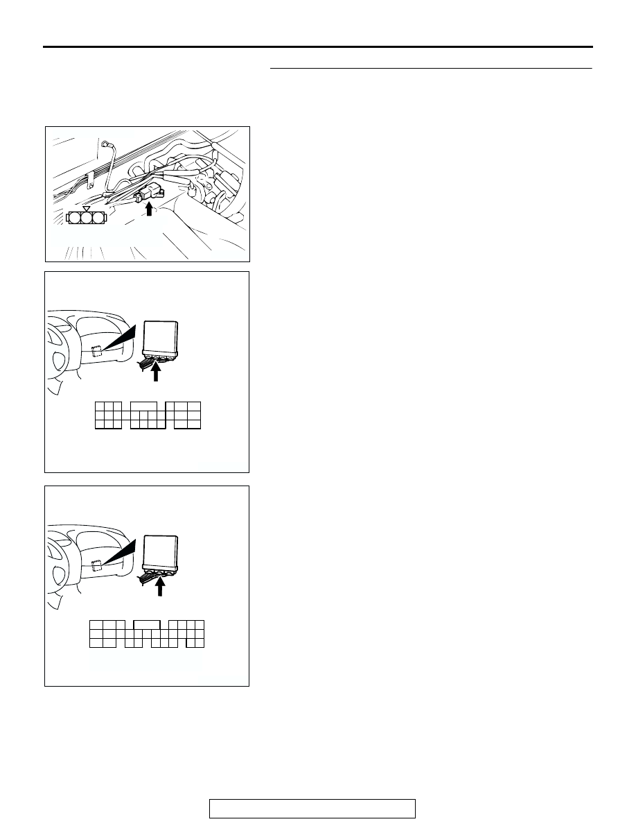
STEP 9. Check for open circuit between manifold absolute 
pressure sensor connector B-04 (terminal No. 2) and ECM 
connector C-58 (terminal No. 49) <M/T> or PCM connector 
C-55 (terminal No. 57) <A/T>.
Q: Is the harness wire in good condition?

YES : Replace the ECM or PCM. Then go to Step 12.
NO :  Repair it. Then go to Step 12.

AK103763

2 1

3

CONNECTOR: B-04

AC

B-04(B)

HARNESS CONNECTOR:
COMPONENT SIDE

AK300462

42

43

48

49

50

51

52

53

54

55

56

57

46 45 44

58

59

60

61

62

63

64

65

66

47

41

CONNECTOR: C-55 <A/T>

C-55 (GR)

AB

HARNESS CONNECTOR:
COMPONENT SIDE

AK300748

65

43
50

42
49

41
48
60

61

64

46

47

58

59

67

68

45

56
66

52 51

44

53

62

54

63

57

55

CONNECTOR: C-58 <M/T>

AB

C-58 (GR)

HARNESS CONNECTOR:
COMPONENT SIDE

MULTIPORT FUEL INJECTION (MFI) DIAGNOSIS

TSB Revision

MULTIPORT FUEL INJECTION (MFI) <3.0L>

13B-100

STEP 10. Check connector B-04 at manifold absolute 
pressure sensor for damage.
Q: Is the connector in good condition?

YES : Go to Step 11.
NO :  Repair or replace it. Refer to GROUP 00E, Harness 

Connector Inspection 

P.00E-2

. Then go to Step 12.

STEP 11. Check connector C-62 at ECM <M/T> or C-59 at 
PCM <A/T> for damage.
Q: Is the connector in good condition?

YES : Replace the manifold absolute pressure sensor. Then 

go to Step 12.

NO :  Repair or replace it. Refer to GROUP 00E, Harness 

Connector Inspection 

P.00E-2

. Then go to Step 12.

AK103763

2 1

3

CONNECTOR: B-04

AC

B-04(B)

HARNESS CONNECTOR:
COMPONENT SIDE

AK300460

98

78

71

88

89

76

77

72
79
91

73
80

74

75

81
92

82

83

93

84

85

94

86

87

95

96

90

97

CONNECTOR: C-59 <A/T>

C-59 (GR)

AB

HARNESS CONNECTOR:
COMPONENT SIDE

AK300445

80

87

81

94

85

82

84

93

86

98

99

74

92

73

83

88

91

95

97 96

100

89

78

71

90

76

77

75

72
79

CONNECTOR: C-62 <M/T>

C-62 (GR)

AB

HARNESS CONNECTOR:
COMPONENT SIDE

MULTIPORT FUEL INJECTION (MFI) DIAGNOSIS

TSB Revision

MULTIPORT FUEL INJECTION (MFI) <3.0L>

13B-101

STEP 12. Test the OBD-II drive cycle.
(1) Carry out a test drive with the drive cycle pattern. Refer to , 

Diagnostic Function 

− OBD-II Drive Cycle − Procedure 6 − 

Other Monitor 

P.13B-7

.

(2) Check the diagnostic trouble code (DTC).
Q: Is DTC P0108 set?

YES : Retry the troubleshooting.
NO :  The inspection is complete.

DTC P0111: Intake Air Temperature Circuit Range/Performance Problem

AK300838

2 3

7

4 5 6

1

BR

O

W

N

RED-BLUE

34 <M/T>*1
16 <A/T>*3

62 <M/T>*2
64 <A/T>*4

B-14

INTAKE AIR TEMPERATURE SENSOR
(INCORPORATED IN VOLUME 
AIRFLOW SENSOR)

ENGINE CONTROL MODULE (ECM) <M/T>
OR
POWERTRAIN CONTROL MODULE (PCM) <A/T>

5

6

5 V

65

43
50

42
49

41
48
60 61

64

46 47
58 59
67 68

45

56
66

52

51

44

53

62

54

63

57

55

C-58 <M/T>
(MU803782)

C-55 <A/T>
(MU803781)

42 43
48 49 50 51 52 53 54 55 56 57

46

45

44

58 59

60 61 62 63

64 65 66

47

41

Intake Air Temperature Sensor Circuit

C-51 <M/T>, C-52 <A/T>
         (MU803784)

2

3 4

5 6

7 8

9

11 12 13 14 15 16 17 18 19 20

30

21 22 23

24 25

26 27 28 29

3132 33

34 35

1

10

NOTE
*1: ECM connector C-51 <M/T>
*2: ECM connector C-58 <M/T>
*3: PCM connector C-52 <A/T>
*4: PCM connector C-55 <A/T>

AK300053

CONNECTOR: B-14

AD

B-14 (B)

INTAKE AIR
TEMPERATURE
SENSOR

AK300091

CONNECTORS: C-51, C-58 <M/T>

ECM

AB

C-51 (GR)

C-58 (GR)

MULTIPORT FUEL INJECTION (MFI) DIAGNOSIS

TSB Revision

MULTIPORT FUEL INJECTION (MFI) <3.0L>

13B-102

.

CIRCUIT OPERATION

• Approximately 5 volts are applied to the intake air 

temperature sensor output terminal (terminal No. 
6) from the ECM (terminal No. 62) <M/T> or PCM 
(terminal No. 64) <A/T> via the resistor in the 
ECM <M/T> or PCM <A/T>. The ground terminal 
(terminal No. 5) is grounded with ECM (terminal 
No. 34) <M/T> or PCM (terminal No. 16) <A/T>.

• The intake air temperature sensor is a negative 

temperature coefficient type of resistor. When the 
intake air temperature rises, the resistance 
decreases.

• The intake air temperature sensor output voltage 

increases when the resistance increases and 
decreases when the resistance decreases.

.

TECHNICAL DESCRIPTION

• The intake air temperature sensor converts the 

intake air temperature to a voltage.

• The ECM <M/T> or PCM <A/T> checks whether 

this voltage is within a specified range.

.

DESCRIPTIONS OF MONITOR METHODS
Intake air temperature sensor output voltage does 

not change when specified go/stop operations 
are repeated.

.

MONITOR EXECUTION
Continuous

.

MONITOR EXECUTION CONDITIONS (Other 
monitor and Sensor)

Other Monitor (There is no temporary DTC stored 

in memory for the item monitored below)

• Not applicable

Sensor (The sensor below is determined to be 

normal)

• Not applicable

.

AK300244

CONNECTORS: C-52, C-55 <A/T>

AB

PCM

C-52 (GR)

C-55 (GR)


Content   ..  387  388  389  390   ..