Mitsubishi Eclipse. Manual - part 180
MULTIPORT FUEL INJECTION (MFI) DIAGNOSIS
TSB Revision
MULTIPORT FUEL INJECTION (MFI) <2.4L>
13A-213
DTC SET CONDITIONS
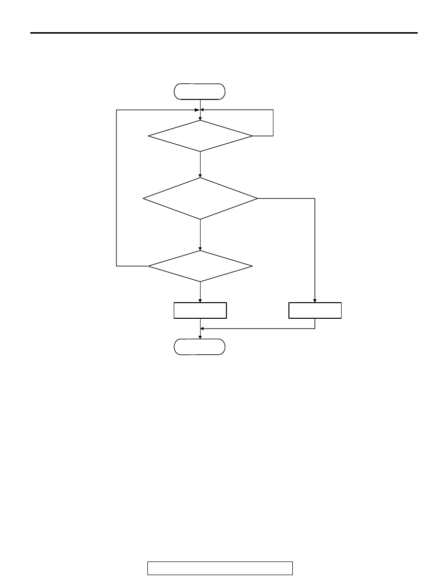
Logic Flow Chart
.
Check Conditions
• Engine coolant temperature is between −10°C
(14
°F) and 77°C (171°F) when the engine is
started.
• The engine coolant temperature − intake air tem-
perature is 5
°C (9°F) or less when the engine is
started.
• The intake air temperature when the engine is
started
− intake air temperature is 5°C (9°F) or
less.
• The volume airflow sensors output frequency is in
the low frequency (50
− 100 Hz or less) state for
300 seconds or less.
Judgment Criteria
• The time for the engine coolant temperature to
rise to 77
°C (171°F) takes longer than approxi-
mately 11 to 22 minutes.
• The PCM monitors for this condition once during
the drive cycle.
.
OBD-ll DRIVE CYCLE PATTERN
None.
.
TROUBLESHOOTING HINTS (The most likely
causes for this code to be set are: )
• The thermostat is faulty
• ECM <M/T> failed.
• PCM <A/T> failed.
START
END
YES
NO
NO
YES
MALFUNCTION
GOOD
TIME HAVE PASSED
AFTER STARTING?*
ENGINE COOLANT TEMP.
>=77˚C (171˚F)
*: See DTC SET CONDITIONS-JUDGMENT CRITERIA
MONITORING
CONDITIONS?
NO
YES
AK204044