Mitsubishi Canter (FE, FG). Manual - part 15
 

  Index      Mitsubishi     Mitsubishi Canter (FE, FG) - service manual 2013 year


Search            


Content   ..  13  14  15  16   ..


Mitsubishi Canter (FE, FG). Manual - part 15


60

5 Damage prevention 

5.1 Electrical system

MITSUBISHI FUSO body/equipment mounting directives for FE, FG  Issue date: 06. 07. 2012

!

 Only print out complete sections from the current version

i

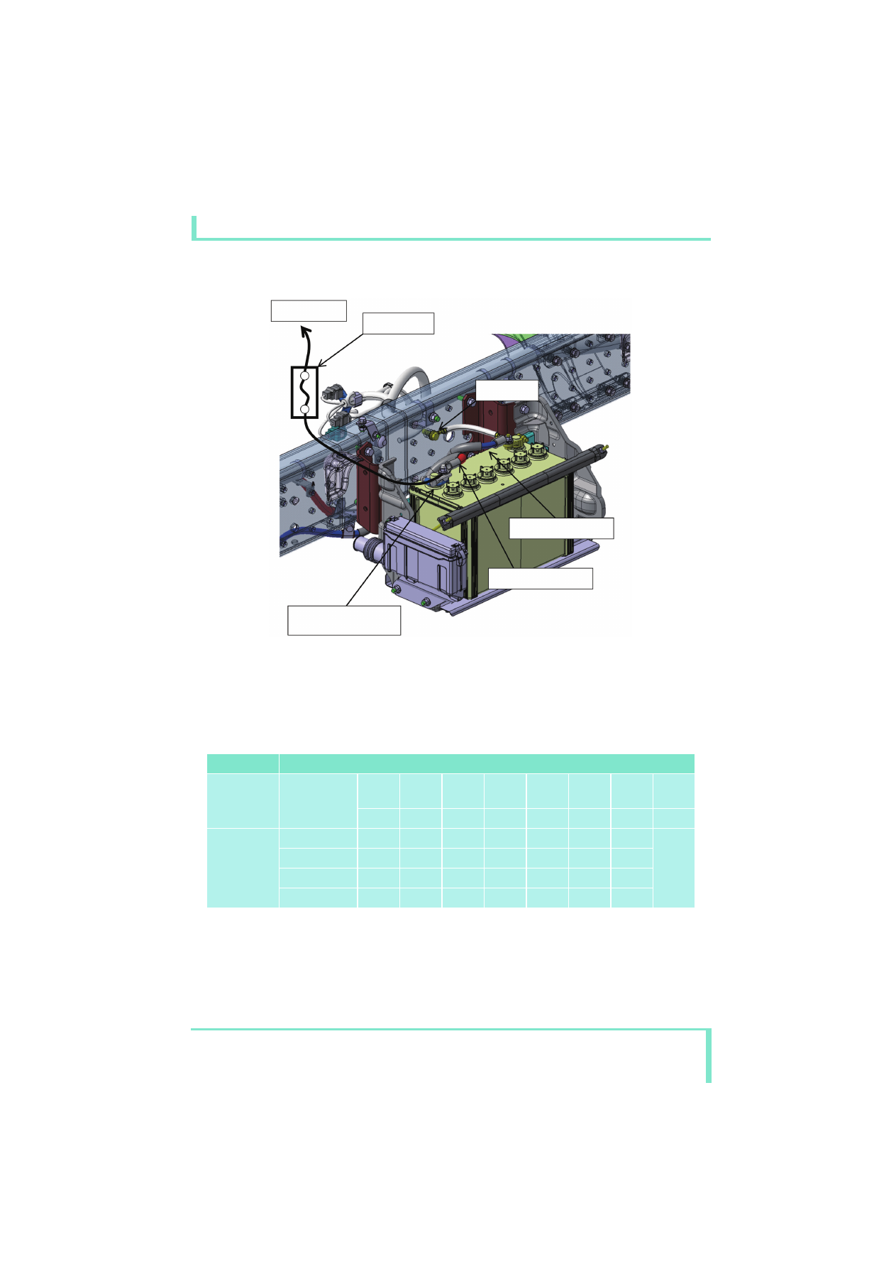
Between battery terminal and fuse

(f) Use a round flat terminal for the power supply terminal and jointly fasten it by using the fixing nut for 

attaching the battery cable terminal.
Only one power supply terminal may be used.
Two or more additional terminals can be loosened, resulting in heat being generated or a short.

List of recommended combinations of fuse capacity and wire size

Note: Keep the continuous permissible current within 70 % of the fuse specifications value.

(E.g.) If the fuse used is 10 A:

10 × 0.7 = 7 (A)
R

 A load of up to 7 A can be used.

Notes:
1. 

҂: Not usable; — : 50 m (165 ft) max

2. AV/AVS wires: general wires; AVX wires: heat-resistant wires

 : Usable ҂ : Not usable

Fuse

Wire size [upper] and wire permissible current [lower]

Type

Specifications

0.3

0.012

0.5

0.020

0.85

0.033

1.25

0.049

2.0

0.079

3.0

0.120

5.0

0.200

(mm

2

)

(in.

2

)

11

14

18

23

31

42

57

(A)

Blade and 
glass tube

5 A

7.5 A

10 A

҂

15 A

҂

҂

Addition on the 

built body

Additional fuse, 

etc.

Terminal for taking power 
on built body side, 
M8 screw

Ground point

Battery cable (-)

Battery cable (+)

61

5 Damage prevention 

5.1 Electrical system

MITSUBISHI FUSO body/equipment mounting directives for FE, FG  Issue date: 06. 07. 2012

!

 Only print out complete sections from the current version

i

5.1.5

Batteries

• Never place any metal objects or tools on the 

batteries.

• There is a risk of short circuit if the positive 

terminal clamp on the connected battery comes 
into contact with vehicle parts. This could cause 
the highly explosive gas mixture to ignite. You and 
others could be seriously injured as a result.

• When disconnecting the batteries, always 

disconnect the negative terminal clamp first and 
then the positive terminal.

• When connecting the batteries, always connect the 

positive terminal clamp first and then the negative 
terminal.

• Incorrect polarity of the supply voltage can cause 

irreparable damage to the control units.

• Never start the engine without a connected battery 

(battery terminals tightened).

• Do not disconnect or remove the battery terminals 

while the engine is running.

• If the batteries are flat, the engine can be jump-

started using jump leads connected to the batteries 
of another vehicle. Observe the Instruction Manual. 
Do not use a quick charger for jump-starting.

• Only tow-start the vehicle with the batteries 

connected.

• Quick-charge the batteries only after 

disconnecting them from the vehicle's electrical 
system. Both the positive and negative terminals 
must be disconnected.

5.1.6

Lines, plug connections and control units

• A plug connection must not be unplugged from or 

plugged into the control unit(s) while the ignition is 
on.

• Lines must be protected from heat by means of 

insulation.

• Route cables in such a way that chafing cannot 

occur, particularly at crossover points and sharp 
edges. If necessary, use cable ducts, insulating 
loom, or guide pipes.

• Do not carry out tests at connector terminals using 

unsuitable tools (test probes, wire ends, etc.). This 
may lead to contact damage and subsequent 
problems. Use suitable test leads.

• The contact persons must be consulted if a battery 

isolating switch is to be retrofitted 

컄 page 15.

i

Installing additional electrical consumers 
컄 page 100.

62

5 Damage prevention 

5.2 Brake hoses/cables and lines

MITSUBISHI FUSO body/equipment mounting directives for FE, FG  Issue date: 06. 07. 2012

!

 Only print out complete sections from the current version

i

5.2 Brake hoses/cables and lines

• Fuel and hydraulic lines and brake hoses must be 

covered or removed if necessary before carrying 
out any welding, drilling and grinding work and 
before working with cutting discs.

• After installing fuel lines, hydraulic lines and brake 

hoses, the potentially affected system must be 
tested for pressure loss and leaks.

• No other lines may be attached to brake hoses.
• Lines must be protected from heat by means of 

appropriate insulation.

• Line routing must be designed to prevent any 

pressure loss.

Comply with all federal, state, and local regulations 
and codes.

a

Risk of accident

Work carried out incorrectly on the brake hoses, 
cables and lines may impair their function. This may 
lead to the failure of components or parts relevant 
to safety.

63

5 Damage prevention 

5.3 Mobile communications systems

MITSUBISHI FUSO body/equipment mounting directives for FE, FG  Issue date: 06. 07. 2012

!

 Only print out complete sections from the current version

i

5.3 Mobile communications systems

United States Federal Communication Commission 
and Canadian National & Provincial communication 
regulations as well as the equipment manufacturer's 
information and installation specifications must be 
observed.

If mobile communication systems (e.g. telephone, 
CB radio) are retrofitted, the following requirements 
must be fulfilled in order to avoid malfunctions 
developing on the vehicle at a later stage.

Equipment

• The equipment must have official approval and 

meet FCC regulations for power, operating 
frequency, and interference.

• The equipment must be permanently installed.
• Operation of portable or mobile equipment inside 

the cab is only permitted if this equipment is 
connected to a permanently installed external 
aerial.

• The transmitter must be installed separately from 

all other vehicle electronics.

• Protect equipment from moisture.
• Observe the permissible operating temperature.
• Protect the equipment against severe mechanical 

vibrations.

Aerial (for two-way radio sets)

• The  aerial  must  be  officially licensed.

Connection and wiring

• The connection should be made directly to 

teriminal inside cab 

컄 page 103.

• Disconnect the unit from the electrical system 

before jump-starting.

• Cables should be wired via the shortest possible 

route (not looped) and twisted.

• Ensure that the system has a good ground 

connection to the body (aerial and equipment).

• The aerial and connecting cables between the 

transmitter, receiver and control panel must be 
routed separately from the vehicle wiring harness 
in the vicinity of the body ground.

• Make sure that the aerial cable is not kinked or 

crushed.

i

The notes on operating safety and vehicle safety in 
Section 1 "Introduction" 

컄 page 10 and 컄 page 11 

must be complied with.


Content   ..  13  14  15  16   ..