Mitsubishi Grandis. Manual - part 929
TROUBLESHOOTING
TRACTION CONTROL/ACTIVE STABILITY CONTROL SYSTEM
35C-41
STEP 8. Check whether the diagnosis code is
reset.
Check again if the diagnosis code is set.
(1) Turn the ignition switch to the "ON" position.
(2) Erase the diagnosis code.
(3) Turn the ignition switch to the "LOCK" (OFF)
position.
(4) Turn the ignition switch to the "ON" position.
(5) Drive the vehicle at 20 km/h or more for 30
seconds or more.
(6) Check if the diagnosis code is set.
(7) Turn the ignition switch to the "LOCK" (OFF)
position.
Q: Is code No.C1226, C1231, C1236, C1241, C1246,
C1251, C1256, C1261, C1300, C1305, C1310 or
C1315 set?
YES :
Go to Step 1.
NO :
The procedure is complete.
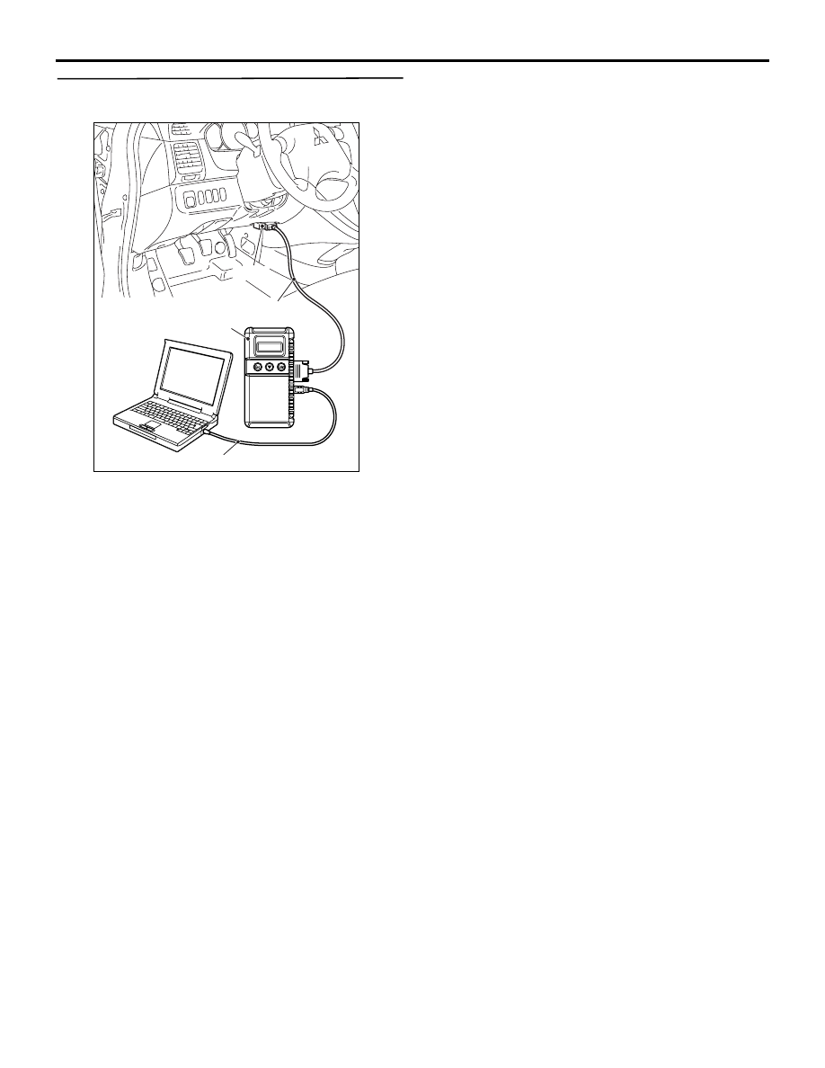
AC302297
AC310120
AB
MB991827
16-pin
MB991910
MB991824