Mitsubishi Grandis. Manual - part 406


  Index      Mitsubishi     Mitsubishi Grandis - service repair manual


Search            


Content   ..  404  405  406  407   ..


Mitsubishi Grandis. Manual - part 406


TOWING AND HOISTING

GENERAL

00-30

Plate type lift

CAUTION

Insert a spacer between the notch and the lift to 
avoid damage to the side sill garnish. Be careful 
not to contact the spacer against the side sill.
Support the notch with a spacer (100-mm width, 
100-mm height and 200-mm depth).

TOWING AND HOISTING

M1001000800421

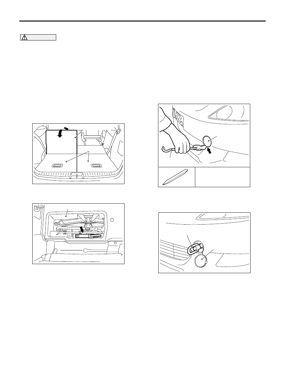
HOW TO SECURE THE TOWING HOOK

When towing this vehicle, attach the towing hook 
according to the procedure below.

1. Fold the third seat and open the luggage floor 

board.

2. Withdraw the towing hook and jack bar from the 

tool box under the luggage floor.

3. Insert special tool MB990784 (Ornament 

Remover) or a jack bar as shown, and remove the 
towing cover from the front bumper.

4. Secure the towing hook.

STANDARD PART/TIGHTENING-TORQUE TABLE

M1001001100447

Each torque value in the table is a standard value for 
tightening under the following conditions.

1. Bolts, nuts and washers are all made of steel and 

plated with zinc.

2. The threads and bearing surface of bolts and 

nuts are all in dry condition.

The values in the table are not applicable:

1. If toothed washers are inserted.
2. If plastic parts are fastened.
3. If bolts are tightened to plastic or die-cast 

inserted nuts.

4. If self-tapping screws or self-locking nuts are 

used.

AC302278

Luggage floor board

Third seat

AC

AC302279

AC

Tool box

AC313594

AB

Jack bar

Towing cover

MB990784: Special tool 
(Ornament Remover)

AC302281

AC

Towing hook

Towing cover

STANDARD PART/TIGHTENING-TORQUE TABLE

GENERAL

00-31

Standard bolt and nut tightening torque 

FLANGE BOLT AND NUT TIGHTENING TORQUE 

NOTE: 

.

Be sure to use only the specified bolts and nuts, and always tighten them to the specified torques.

Bolts marked with indications such as 4T or 7T are reinforced bolts. The larger the number, the greater the 
bolt strength.

Thread size

Torque   N

m

Bolt nominal 
diameter   (mm)

Pitch   
(mm)

Head mark "4"

Head mark "7"

Head mark "8"

M5

0.8

2.5 

± 0.5

5.0 

± 1.0

6.0 

± 1.0

M6

1.0

5.0 

± 1.0

9.0 

± 2.0

10 

± 2

M8

1.25

12 

± 2

22 

±  4

25 

± 4

M10

1.25

24 

± 4

44 

± 10

53 

± 7

M12

1.25

41 

± 8

83 

± 12

98 

± 12

M14

1.5

73 

± 12

140 

± 20

155 

± 25

M16

1.5

110 

± 20

210 

± 30

235 

± 35

M18

1.5

165 

± 25

300 

± 40

340 

± 50

M20

1.5

225 

± 35

410 

± 60

480 

± 70

M22

1.5

300 

± 40

555 

± 85

645 

± 95

M24

1.5

395 

± 55

735 

± 105

855 

± 125

Thread size

Torque   N

m

Bolt nominal 
diameter   (mm)

Pitch   
(mm)

Head mark "4"

Head mark "7"

Head mark "8"

M6

1.0

5.0 

± 1.0

10 

± 2

12 

± 2

M8

1.25

13 

± 2

24 

± 4

27 

± 5

M10

1.25

26 

± 4

49 

± 9

58 

± 7

M10

1.5

24 

± 4

45 

± 8

55 

± 10

M12

1.25

46 

± 8

95 

± 15

105 

± 15

M12

1.75

43 

± 8

83 

± 12

98 

± 12

HOW TO READ WIRING DIAGRAMS

GENERAL <ELECTRICAL>

00E-2

HOW TO READ WIRING DIAGRAMS

COMPOSITION AND CONTENTS OF 
WIRING DIAGRAMS

M1001012800031

In each section, all specifications are listed, including optional specifications. Accordingly, some 
specifications may not be applicable for individual vehicles.

HOW TO READ CONFIGURATION 
DIAGRAMS

M1001006400078

The wiring harness diagrams clearly show the connector locations and harness routings at each site on 
actual vehicles.

Section

Basic contents

Component 
locations

Locations are shown for each point of relays, ECUs, sensors, solenoid valves, 
inspection terminals, fusible links, fuses, etc. In the part’s lists, parts are listed in 
alphabetical order.

Configuration 
diagrams

Connector locations and harness wiring configurations on actual vehicles are 
illustrated.

Circuit diagrams

Circuits from power source to earth are shown completely, classified according to 
system. There is a main division into power source circuits and circuits classified by 
system. The circuits classified by system also include operation and troubleshooting 
hints.

• Junction block

The entire circuit for the junction block is described, because only the part of the 
junction block needed is normally shown in each circuit diagram.

• Joint connectors

The internal circuits for all joint connectors are described, because only the part 
needed is shown in each circuit diagram.

• Power source circuits

Circuits from the battery to fusible link, fuse, ignition switch, etc are shown.

• Circuits classified by system

For each system, the circuits are shown from fuse to earth, excluding the power 
source sections.


Content   ..  404  405  406  407   ..