Mitsubishi Grandis. Manual - part 275
INPUT SIGNAL PROCEDURES
SMART WIRING SYSTEM (SWS) USING SWS MONITOR
54C-562
Inspection Procedure Q-23: Each switch signal of the keyless entry transmitter is not received.
CAUTION
Whenever the ECU is replaced, ensure that the
input signal circuit is normal.
COMMENTS ON TROUBLE SYMPTOM
Input signal from the keyless entry transmitter is
used to operate the keyless entry system. If the
signal is abnormal, the keyless entry system will not
work normally.
• Keyless entry system
• Keyless entry hazard answerback
• Multimode keyless entry system
POSSIBLE CAUSES
• Malfunction of the keyless entry transmitter
• Defective battery of the keyless entry transmitter
• Malfunction of the ETACS-ECU
DIAGNOSIS PROCEDURE
Step 1. Pulse check
Check whether the ETACS-ECU receives signal from
a transmitter or not. For this check, you should use
the 2-button-type transmitter (integrated with a key),
which cover screw is silver and has already been
registered.
NOTE: For how to register the keyless entry
transmitter encrypted code, refer to GROUP 42
−
On-vehicle Service
.
OK: The MUT-III sounds or the voltmeter
needle fluctuates.
Q: Is the check result normal?
YES :
Go to Step 2.
NO :
Go to Step 4.
Step 2. Check the transmitter battery.
Refer to GROUP 42
− Keyless entry system
Q: Is the check result normal?
YES :
Go to Step 3.
NO :
Replace the keyless entry transmitter
battery.
Step 3. Register the encrypted code, and then
retest the system.
(1) Register the keyless entry transmitter again.
(2) Check that each signal is received from the
keyless entry transmitter.
Q: Is the check result normal?
YES :
The trouble can be an intermittent
malfunction (Refer to GROUP 00
− How to
Cope with Intermittent Malfunction
NO :
Replace the keyless entry transmitter.
Step 4. Retest the system.
Check that each signal is received from the keyless
entry transmitter.
Q: Is the check result normal?
YES :
The trouble can be an intermittent
malfunction (Refer to GROUP 00
− How to
Cope with Intermittent Malfunction
NO :
Replace the ETACS-ECU.
W3Z10E39AA
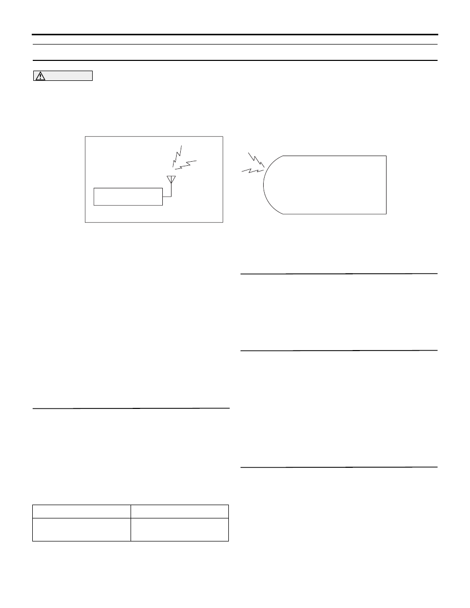
KEYLESS ENTRY
TRANSMITTER
KEYLESS ENTRY
RECEIVER
ETACS-ECU
Transmitter Input Circuit
System switch
Check condition
Keyless entry transmitter
"LOCK/UNLOCK" switch
When the switch is
turned from off to on