Mitsubishi Grandis. Manual - part 269


  Index      Mitsubishi     Mitsubishi Grandis - service repair manual


Search            


Content   ..  267  268  269  270   ..


Mitsubishi Grandis. Manual - part 269


INPUT SIGNAL PROCEDURES

SMART WIRING SYSTEM (SWS) USING SWS MONITOR

54C-538

YES : 

Diagnose the combination meter (Refer to 

GROUP 54A 

− Combination meter 

P.54A-35

).

NO : 

Go to Step 3.

Step 3. Connector check: D-23 seat belt switch 
(LH) connector

Q: Is the check result normal?

YES : 

Go to Step 4.

NO : 

Repair the defective connector.

Step 4. Check the seat belt switch (LH).

Refer to GROUP 52A 

− Front seat belt 

P.52A-36

.

Q: Is the check result normal?

YES : 

Go to Step 5.

NO : 

Replace the inner seat belt (driver's side).

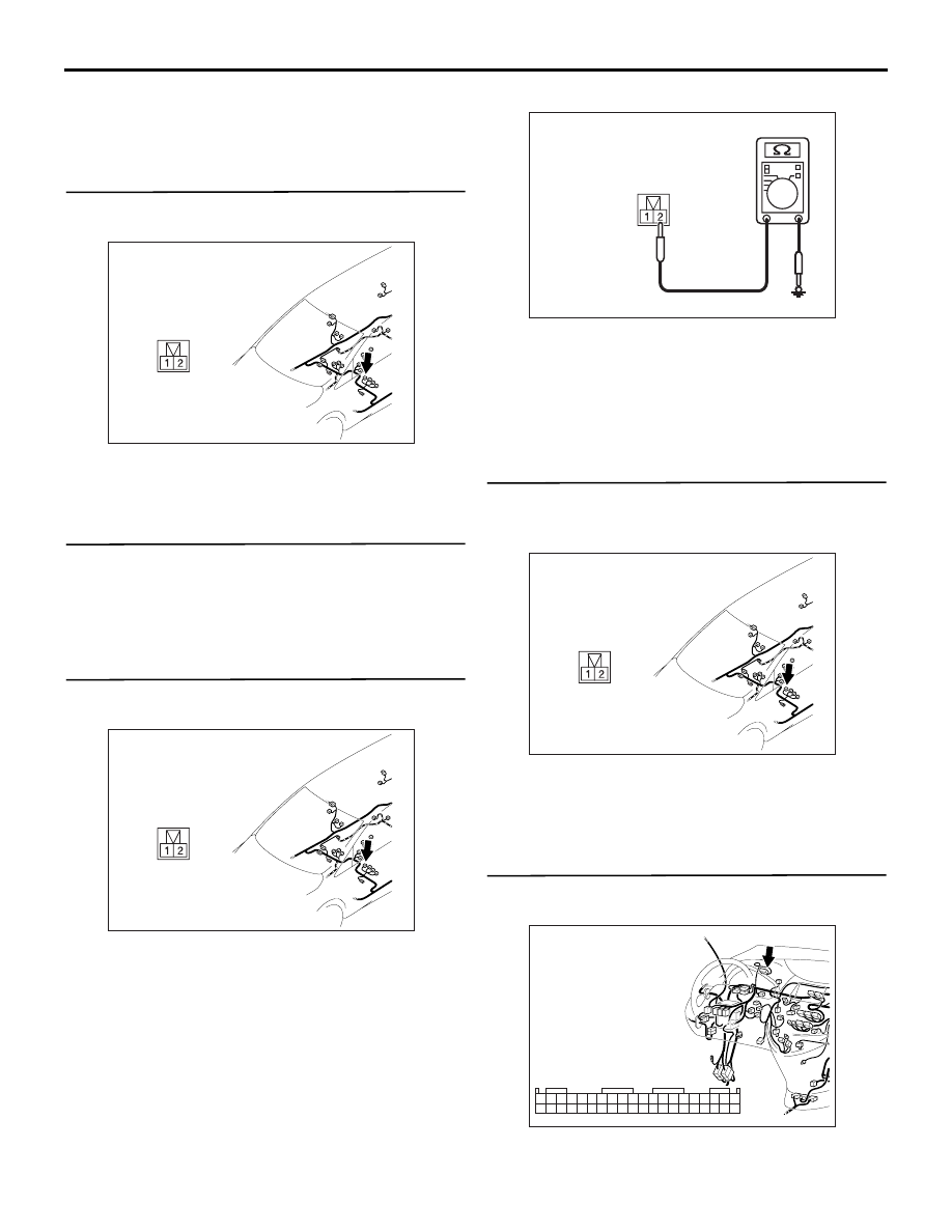
Step 5. Resistance measurement at the D-23 seat 
belt switch (LH) connector.

(1) Disconnect the connector, and measure at the 

wiring harness side.

(2) Resistance between D-23 seat belt switch (LH) 

connector terminal No.2 and body earth

OK: 2 

 or less

Q: Is the check result normal?

YES : 

Go to Step 7.

NO : 

Go to Step 6.

Step 6. Check the wiring harness between D-23 
seat belt switch (LH) connector terminal No.2 and 
body earth.

• Check the earth wires for open circuit.

Q: Is the check result normal?

YES : 

Replace the inner seat belt (driver's side).

NO : 

Repair the wiring harness.

Step 7. Connector check: C-02 combination 
meter connector

Q: Is the check result normal?

AC312051

Connector: D-23 <LHD>

AB

AC312051

Connector: D-23 <LHD>

AB

AC312730AO

Connector D-23
(Harness side)

AC312051

Connector: D-23 <LHD>

AB

AC312031

Connector: C-02 <LHD>

AK

1

2

3

4

5

6

7

8

9

10

11

12

13

14

15

16

17

18

19

20
40393837

23

24

25

26

27

28

29

30

31

32

33

34

35

36

2221

INPUT SIGNAL PROCEDURES

SMART WIRING SYSTEM (SWS) USING SWS MONITOR

54C-539

YES : 

Go to Step 8.

NO : 

Repair the defective connector.

Step 8. Check the wiring harness from D-23 seat 
belt switch (LH) terminal No.1 to C-02 
combination meter connector terminal No.32.

NOTE: 

Prior to the wiring harness inspection, check 
intermediate connector C-16, and repair if necessary.

• Check the input line for open circuit.

Q: Is the check result normal?

YES : 

Go to Step 9.

NO : 

Repair the wiring harness.

Step 9. ETACS switch data by using the SWS 
monitor

Check the input signal from the driver's seat belt 
switch.

• Ignition switch: ON

• Driver's seat belt switch: ON (Unfastened) → 

OFF (Fastened)

OK: Normal condition is displayed.

Q: Is the check result normal?

YES : 

The trouble can be an intermittent 

malfunction (Refer to GROUP 00 

− How to 

Cope with Intermittent Malfunction 

P.00-5

).

NO : 

Go to Step 10.

Step 10. Retest the system.

After the ETACS-ECU is replaced, check that the 
driver's seat belt switch signal is received.
(1) Replace the ETACS-ECU.
(2) Check that the driver's seat belt switch signal is 

received.

Q: Is the check result normal?

YES : 

The trouble can be an intermittent 

malfunction (Refer to GROUP 00 

− How to 

Cope with Intermittent Malfunction 

P.00-5

).

NO : 

Replace the combination meter.

AC312043

Connector: C-02 <RHD>

AK

Harness side

1

2

3

4

5

6

7

8

9

10

11

12

13

14

15

16

17

18

19

20
40 3938 37

23

24

25

26

27

28

29

30

31

32

33

34

35

36

22 21

AC312051

Connector: D-23 <LHD>

AB

AC312033

Connector: C-16 <LHD>

AB

9

21

33

35

24

12

3 4

7

8

5 6

39

28

41

30

18

4243

31

1920

32

40

29

1617

38

27

15

37

36

26

14

13

25

2

1

34

23

11

10

22

Item No.

Item name

Normal condition

Item 12

SEAT BELT SW

from ON to OFF

INPUT SIGNAL PROCEDURES

SMART WIRING SYSTEM (SWS) USING SWS MONITOR

54C-540

Inspection Procedure Q-19: The driver's seat belt switch signal is not received. <RH drive vehicles>

CAUTION

Whenever the ECU is replaced, ensure that the 
input signal circuit is normal.

COMMENTS ON TROUBLE SYMPTOM

Input signal from the driver's seat belt switch signal is 
used to operate the central door locking function. If 
the signal is abnormal, the central door locking 
function will not work normally.

POSSIBLE CAUSES

• Malfunction of the driver's seat belt switch

• Malfunction of the ETACS-ECU

• Malfunction of the combination meter

• Damaged harness wires and connectors

DIAGNOSTIC PROCEDURE

Step 1. MUT-III CAN bus diagnostics

Use the MUT-III to diagnose the CAN bus lines.

Q: Is the check result normal?

YES : 

Go to Step 2.

NO : 

Repair the CAN bus line (Refer to GROUP 
54D 

− Diagnosis 

P.54D-16

).

Step 2. MUT-III diagnosis code

Check whether the combination meter-related 
diagnosis code is set.

Q: Is the diagnosis code set?

YES : 

Diagnose the combination meter (Refer to 

GROUP 54A 

− Combination meter 

P.54A-35

).

NO : 

Go to Step 3.

COMBINATION METER

SEAT BELT
SWITCH (RH)

Wire colour code
B : Black     LG : Light green
G : Green     L : Blue
W : White     Y : Yellow
SB : Sky blue     BR : Brown
O : Orange     GR : Gray
R : Red     P : Pink     V : Violet

Driver's Seat Belt Switch Input Circuit <RHD>

ETACS-ECU

CAN COMMUNICATION LINE
(CAN_L LINE)

CAN COMMUNICATION LINE
(CAN_H LINE)

INPUT SIGNAL PROCEDURES

SMART WIRING SYSTEM (SWS) USING SWS MONITOR

54C-541

Step 3. Connector check: D-26 seat belt switch 
(RH) connector

Q: Is the check result normal?

YES : 

Go to Step 4.

NO : 

Repair the defective connector.

Step 4. Check the seat belt switch (RH).

Refer to GROUP 52A 

− Front seat belt 

P.52A-36

.

Q: Is the check result normal?

YES : 

Go to Step 5.

NO : 

Replace the inner seat belt (driver's side).

Step 5. Resistance measurement at the D-26 seat 
belt switch (RH) connector.

(1) Disconnect the connector, and measure at the 

wiring harness side.

(2) Resistance between D-26 seat belt switch (LH) 

connector terminal No.2 and body earth

OK: 2 

 or less

Q: Is the check result normal?

YES : 

Go to Step 7.

NO : 

Go to Step 6.

Step 6. Check the wiring harness between D-26 
seat belt switch (RH) connector terminal No.2 
and body earth.

• Check the earth wires for open circuit.

Q: Is the check result normal?

YES : 

Replace the inner seat belt (driver's side).

NO : 

Repair the wiring harness.

Step 7. Connector check: C-02 combination 
meter connector

Q: Is the check result normal?

YES : 

Go to Step 8.

NO : 

Repair the defective connector.

AC312058

Harness side

AC

Connector: D-26 <RHD>

AC312058

Harness side

AC

Connector: D-26 <RHD>

AC312730AP

Connector D-26
(Harness side)

AC312058

Harness side

AC

Connector: D-26 <RHD>

AC312043

Connector: C-02 <RHD>

AK

Harness side

1

2

3

4

5

6

7

8

9

10

11

12

13

14

15

16

17

18

19

20
40 3938 37

23

24

25

26

27

28

29

30

31

32

33

34

35

36

22 21


Content   ..  267  268  269  270   ..