Content .. 1000 1001 1002 1003 ..
Mitsubishi Grandis. Manual - part 1002
TROUBLESHOOTING
SUPPLEMENTAL RESTRAINT SYSTEM (SRS)
52B-60
DIAGNOSIS PROCEDURE
STEP 1. MUT-III CAN bus diagnostics
Use the MUT-III to diagnose the CAN bus lines.
Q: Is the check result normal?
YES :
Go to Step 2.
NO :
Repair the CAN bus line (Refer to GROUP
54D, Diagnosis
STEP 2. Check whether the diagnosis code is
reset.
Check again if the diagnosis code is set.
(1) Erase the diagnosis code.
(2) Ignition: LOCK (OFF) position to ON
(3) On completion, check that the diagnosis code is
not reset.
Q: Is the diagnosis code set?
YES :
Go to Step 3.
NO :
There is an intermittent malfunction such as
poor engaged connector(s) or open circuit
(Refer to GROUP 00, How to Cope with
Intermittent Malfunction
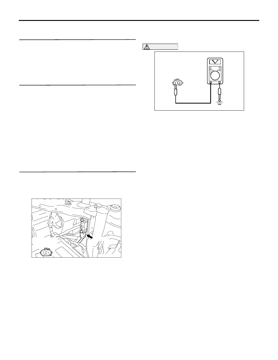
STEP 3. Check the front impact sensor (LH)
power supply circuit. Voltage measurement at the
front impact sensor (LH) connector A-22.
(1) Disconnect the negative battery terminal.
(2) Disconnect front impact sensor (LH) connector
A-22, and measure at the wiring harness side.
(3) Connect the negative battery terminal.
(4) Turn the ignition switch to the "ON" position.
CAUTION
Do not insert a test probe into the terminal from
its front side directly, as the connector contact
pressure may be weakened.
(5) Measure the voltage between A-22 harness side
connector terminal 1 and body earth.
OK: 9 V or more
Q: Is the check result normal?
YES :
Replace the front impact sensor (LH).
(Refer to
).
NO :
Go to Step 4.
AC311405AC
A-22 (Y)
Connector: A-22
Harness side
(front view)
AC311097
A-22 Harness side
connector (rear view)
AE