Mitsubishi L200. Manual - part 890


  Index      Mitsubishi     Mitsubishi L200 - service repair manual 2012 year


Search            


Content   ..  888  889  890  891   ..


Mitsubishi L200. Manual - part 890


TROUBLESHOOTING

AUTOMATIC AIR CONDITIONER

55B-89

STEP 6. Replace the photo sensor and recheck 
the trouble symptom
 Check that the A/C works normally.

Q: Is the check result normal?

YES : 

This diagnosis is complete.

NO : 

Replace the automatic A/C control panel (A/
C-ECU).

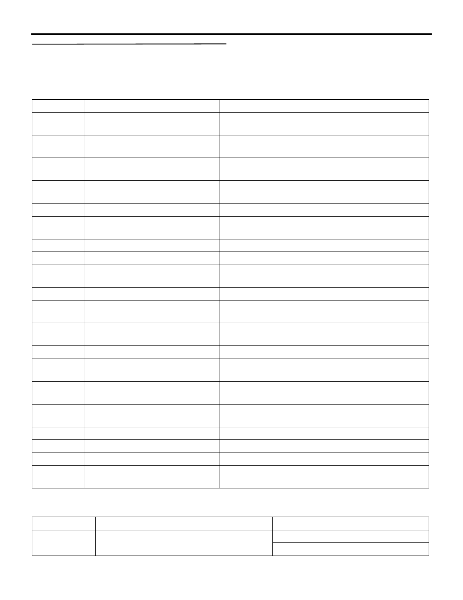
SERVICE DATA REFERENCE TABLE

M1554005101098

Item No.

Check items

Check contents

15

Illumination

Displays the illumination condition of the heater control 
panel.

19

Ambient temperature sensor

Displays the detected temperature of the Ambient 
temperature sensor.

20

Air thermo sensor

Displays the detected temperature of the air thermo 
sensor.

21

Interior temperature sensor

Displays the detected temperature of the Interior 
temperature sensor.

23

Temperature setting

Displays the set temperature.

24

Engine coolant TEMP. sensor

Displays the detected temperature of the Engine coolant 
TEMP. sensor

27

A/C Compressor drive request

Displays the operation of the A/C compressor.

28

Air conditioner switch

Displays the condition of the A/C switch.

30

PTC heater drive request

Displays the condition of the PTC heater drive request 
signal.

34

Idle up request

Displays the idle-up condition.

45

In/out select damp poten (target)

Displays the target position of the inside/outside air 
selection damper.

46

In/out select damp potentiometer

Displays the condition of inside/outside air selection 
damper control motor.

55

Air outlet c/o potentiometer

Displays the set air outlet position.

56

Air outlet c/o potentio. (Target)

Displays the target position of the mode selection 
damper.

60

Rear defogger switch

Displays the condition of the rear window defogger 
switch.

63

Air mix potentiometer

Displays the condition of air mixing damper control 
motor.

67

Photo sensor

Displays the volume of insolation.

68

Front blower fan

Displays the air volume of the blower.

69

Front blower fan (Target)

Displays the target value of the blower motor.

72

Rear defogger relay

Displays the condition of the rear window demister 
relay.

ACTUATOR TEST TABLE

M1554005200393

Item No.

Check items

Drive content

1

A/C compressor drive*

OFF
ON

TROUBLESHOOTING

AUTOMATIC AIR CONDITIONER

55B-90

NOTE: *: Drive at the engine operation

CHECK AT THE A/C-ECU TERMINALS

M1552010302749

42

35

39

38

3132

4041

3334

44

43

3637

AC509349AC

C-43

C-44

2

idle up request*

OFF
ON

4

Rear defogger

OFF
ON

5

In/out select damper

Fresh
Recirc

6

Air mixing damper motor

0% (MAX COOL) 

− 100% (MAX COOL)

7

Front blower fan

0 V (OFF) 

− 12 V (MAX)

8

Air outlet c/o dumper

AUTO
bi-level 1
bi-level 2
bi-level 3
bi-level 4
bi-level 5
DEF
DEF/FOOT 1
DEF/FOOT 2
DEF/FOOT 3
DEF/FOOT 4
DEF/FOOT 5
FACE
FOOT

9

PTC heater drive request

OFF
ON

Item No.

Check items

Drive content

Terminal No.

Check items

Check conditions

Normal conditions

1

Air mix damper 
motor (COOL)

When the front air conditioner is 
moved to the COOL position 

System voltage

When the front air conditioner is 
moved to the HOT position 

− 1 V

2

Mode selection 
damper control 
motor (FACE)

When moving toward FACE 
position

System voltage

When moving toward DEF position  0 

− 1 V

TROUBLESHOOTING

AUTOMATIC AIR CONDITIONER

55B-91

3

Outside/Inside air 
selection damper 
control motor

When the damper is moved to the 
inside air recirculation position

1 V or less 

When the damper is moved to the 
fresh air position

System voltage

4

Outside/Inside air 
selection damper 
control motor

When the damper is moved to the 
inside air recirculation position

System voltage

When the damper is moved to the 
fresh air position

1 V or less

5

Output to the 
engine-ECU

A/C stopped

1 V or less

• A/C switch: ON

• Blower switch: ON

System voltage

6

Rear cooler switch 
(front) indicator

Rear cooler switch (front): ON

System voltage

Rear cooler switch (front): OFF

1.0 V or less

7

Input from diagnosis Ignition switch: ON

Approximately 5 V 

8

Battery power supply Always

System voltage

10

Battery power supply IG2: ON

System voltage

11

Communication with 
combination meter

12

Air mix damper 
motor (HOT)

When the front air conditioner is 
moved to the HOT position 

System voltage

When the front air conditioner is 
moved to the COOL position 

− 1 V

13

Mode selection 
damper control 
motor (DEF)

When moving toward DEF position System voltage
When moving toward FACE 
position 

− 1 V

14

Rear defogger relay IG2: ON

System voltage

15

Rear cooler relay

IG2: ON

System voltage

16

Output to the 
engine-ECU (A/C2)

When the A/C is under low load

System voltage

When the A/C is under high load

1 V or less

18

Front blower relay

IG2: ON

System voltage

22

Earth

Always

1.0 V or less

32

Air mixing damper 
control motor and 
potentiometer input

MAX COOL position 

Approximately 1

33

Mode selection 
damper control 
motor and 
potentiometer input

DEF position

0.5 

− 0.8 V

34

Sensor power 
supply:

Ignition switch: IG2

5 V

35

Power transistor 
(DRAIN)

Air volume control dial: Maximum 
air volume (Preset temperature 
18

°C)

− 2 V

Terminal No.

Check items

Check conditions

Normal conditions

HEATER CONTROL UNIT

AUTOMATIC AIR CONDITIONER

55B-92

HEATER CONTROL UNIT

REMOVAL AND INSTALLATION

M1554014700750

AC809580

1

3

2

AB

36

Power transistor 
(GATE)

Air volume control dial: Maximum 
air volume (Preset temperature 
18

°C)

System voltage

37

Tail lamp relay

Tail lamp: ON

System voltage

38

Sensor earth

Always

1 V or less

39

Air thermo sensor

Sensor probe temperature 25

°C 

(1.5k 

Ω)

2.2 V

40

Interior temperature 
sensor

Sensor probe temperature: 25

°C 

(4k

Ω)

2.1 

− 2.7 V

41

Photo sensor input

43

Rear cooler switch 
(front)

Rear cooler switch (front): ON

System voltage

Rear cooler switch (front): OFF

1 V or less 

44

Earth

Always

1 V or less

Terminal No.

Check items

Check conditions

Normal conditions


Content   ..  888  889  890  891   ..