Mitsubishi L200. Manual - part 698


  Index      Mitsubishi     Mitsubishi L200 - service repair manual 2012 year


Search            


Content   ..  696  697  698  699   ..


Mitsubishi L200. Manual - part 698


FRONT FOG LAMP

CHASSIS ELECTRICAL

54A-159

STEP 4. Check the wiring harness from A-52 
front fog lamp (LH) connector terminal or A-53 
front fog lamp (RH) connector terminal No.1 to 
body earth.

• Check the earth wires for open circuit.

Q: Is the check result normal?

YES : 

Go to Step 7.

NO : 

Repair the wiring harness.

STEP 5. Connector check: Connector check: A-
13X front fog lamp relay connector

Q: Is the check result normal?

YES : 

Go to Step 6.

NO : 

Repair the defective connector.

STEP 6. Check the wiring harness from A-52 
front fog lamp (LH) connector or A-53 front fog 
lamp (RH) connector terminal No.2 to A-13X front 
fog lamp relay connector terminal No.3.

• Check the power supply line for open circuit.

Q: Is the check result normal?

YES : 

Go to Step 7.

NO : 

Repair the wiring harness.

STEP 7. Retest the system.
Check that the front fog lamps illuminate normally.

Q: Is the check result normal?

YES : 

The trouble can be an intermittent 

malfunction (Refer to GROUP 00 

− How to 

use Troubleshooting/inspection Service 
Points 

− How to Cope with Intermittent 

Malfunction ).

NO : 

Replace the front fog lamp(s).
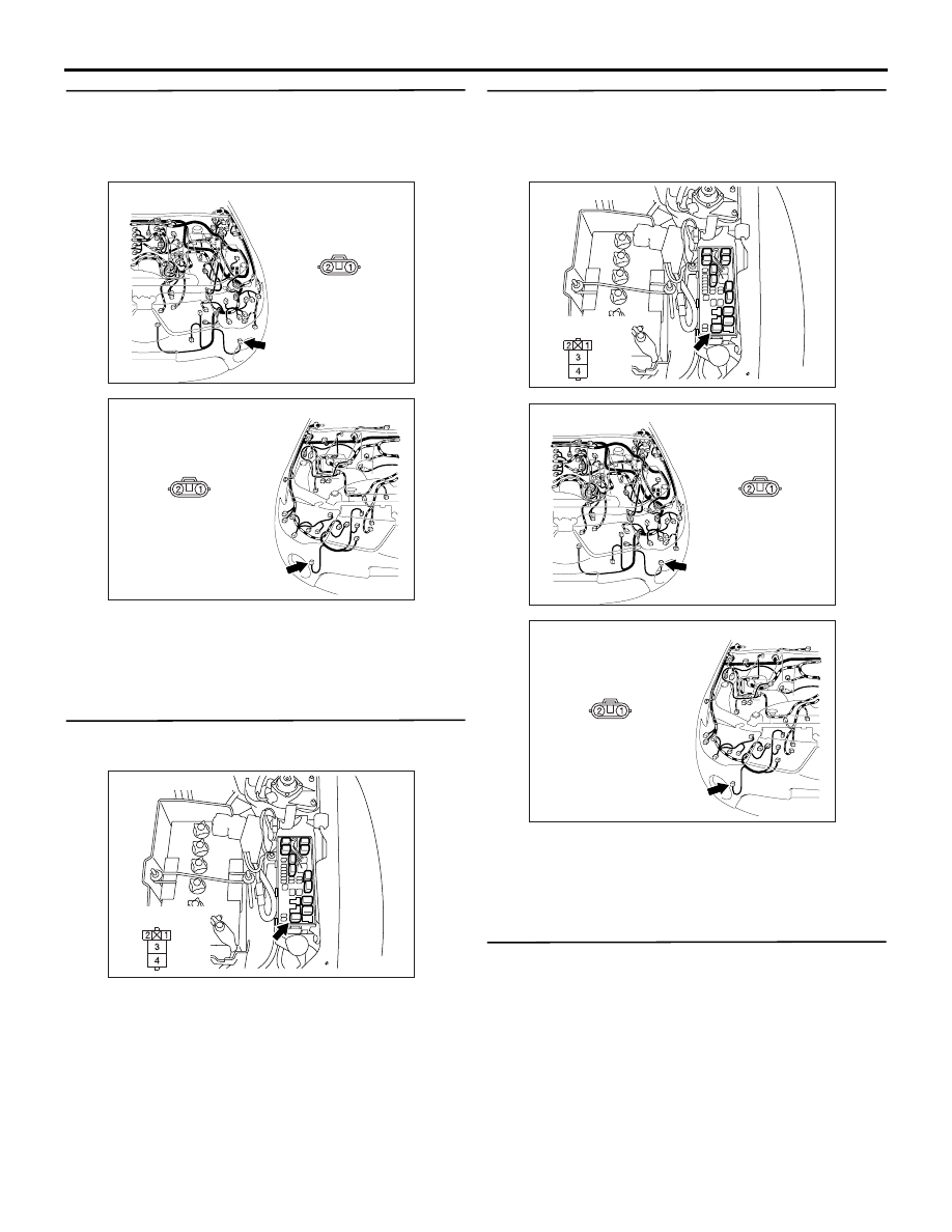
AC903898

AI

Connector: A-52

Harness side

A-52 (B)

AC903897

AI

Connector: A-53

Harness side

A-53 (B)

AC903878

AE

Connector: A-13X

Relay box side

AC903878

AE

Connector: A-13X

Relay box side

AC903898

AI

Connector: A-52

Harness side

A-52 (B)

AC903897

AI

Connector: A-53

Harness side

A-53 (B)

FRONT FOG LAMP

CHASSIS ELECTRICAL

54A-160

ON-VEHICLE SERVICE

FRONT FOG LAMP AIMING

M1540400300680

CAUTION

When marking the aiming adjustment, be sure to 
mask those lamps which are not being adjusted.

1. Measure the centre of the front fog lamps, as 

shown in the illustration.

2. Set the distance between the screen and the 

centre of the front fog lamps as shown in the 
illustration.

3. Inflate the tyres to the specified pressures and 

there should be no other load in the vehicles other 
than driver or substituted weight of approximately 
75 kg placed in the driver’s position.

4. With the engine running at 2,000 r/min, aim the 

front fog lamp.

5. Remove the fog lamp bezel. (Refer to 

P.54A-161

.)

6. Insert a Phillips screwdriver into the service hole 

and place it on the adjusting screw.

7. Adjust the cut off line (boundary between light and 

dark) position to the standard value with the 
adjusting screw.

Standard value:
(Vertical direction) 60 mm (1.15

°) below hori-

zontal (H)

NOTE: The horizontal direction is non-adjustable. If 
the deviation of the light beam axis exceeds the 
standard value, check to be sure that the mounting 
location or some other point is not defective.

AC805341

AD

Front fog lamp centre

<Single cab and vehicles for Russia>

AC800995AC

Front fog lamp
centre

<Vehicles for Europe (except for single cab)>

AC804645

AB

Screen

3 m

Fog lamp centre

Vehicle centre line

AC805332

AD

Adjusting screw

<Single cab and vehicles for Russia>

Phillips screwdriver
(Vertical direction adjustment)

AC800993AC

Phillips screwdriver
(Vertical direction adjustment)

<Vehicles for Europe (except for single cab)>

Adjusting screw

AC312871AC

Distance of
vertical direction

V

H

Lamp centre

Cut off line

High intensity zone

FRONT FOG LAMP

CHASSIS ELECTRICAL

54A-161

REPLACEMENT OF REPLACEABLE BULB

M1540400400557

CAUTION

Don't touch the bulb surface with bare hands or 
dirty gloves. If the bulb surface (glass part) gets 
dirty, clean it with alcohol or thinner immediately 
and dry well, and then install it.
1. Remove the fog lamp bezel and the fog lamp 

assembly. (Refer to 

P.54A-161

.)

2. Disconnect the connector and withdraw the bulb.
3. After replacing the bulb, securely connect the 

connector, and install the fog lamp assembly and 
the fog lamp bezel.

REMOVAL AND INSTALLATION

M1540400500372

<SINGLE CAB AND VEHICLES FOR RUSSIA>

AC800929AB

Fog lamp bulb

Post-installation operation
Check the beam direction of the front fog lamp (Refer to 
Front Fog Lamp Aiming 

P.54A-160

).

AC805351AB

1

2

3

4

0.7 ± 0.0 N·m

FRONT FOG LAMP

CHASSIS ELECTRICAL

54A-162

<VEHICLES FOR EUROPE (EXCEPT FOR SINGLE CAB)>

AC805699

1

Front
bumper
face

AB

Section A - A

Section B - B

Section C - C

Section D - D

Claw

A

A

Claw

Claw

Claw

1

1

1

Front
bumper
face

Front
bumper
face

Front
bumper
face

A

A

A

A

B

B

B B

C

C

C

C

D

D

D

D

1

Removal steps 

1.

Fog lamp bezel

2.

Fog lamp assembly

3.

Bulb

4.

Fog lamp

Removal steps (Continued)

Post-installation operation
Check the beam direction of the front fog lamp (Refer to 
Front Fog Lamp Aiming 

P.54A-160

).

AC801312 AB

1

4

3

2

2.5 ± 0.3 N·m


Content   ..  696  697  698  699   ..