Mitsubishi L200. Manual - part 415


  Index      Mitsubishi     Mitsubishi L200 - service repair manual 2012 year


Search            


Content   ..  413  414  415  416   ..


Mitsubishi L200. Manual - part 415


MASTER CYLINDER ASSEMBLY AND BRAKE BOOSTER ASSEMBLY

BASIC BRAKE

35A-24

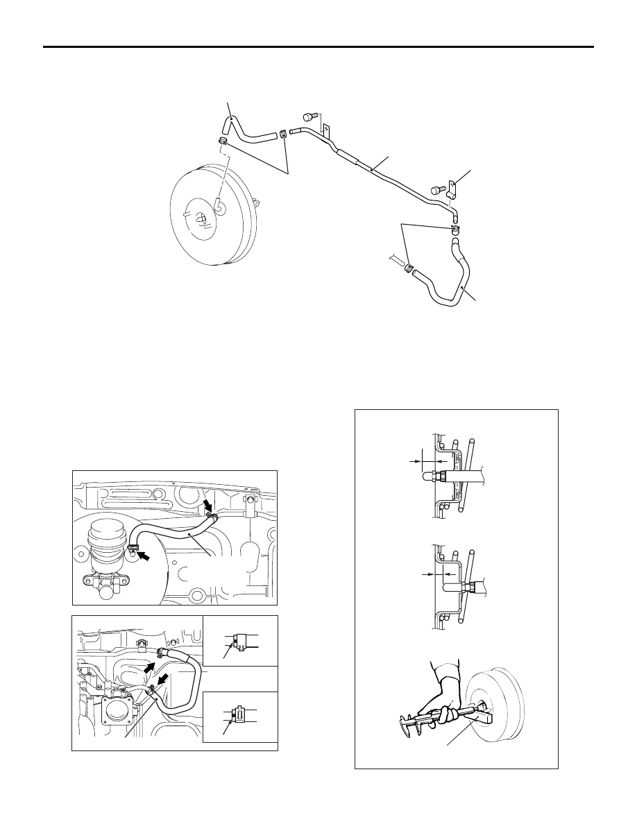
VACUUM HOSE AND VACUUM PIPE

AC805359AB

1

4

3

5

2

6

Removal steps 

>>

A

<<

1.

Vacuum hose (with built-in check 
valve)

2.

Hose clip

>>

A

<<

3.

Vacuum hose

4.

Hose clip

5.

Vacuum pipe

6.

Clamp

INSTALLATION SERVICE POINTS

>>A<< VACUUM HOSE INSTALLATION

AC502302AC

Vacuum hose
(with built-in
check valve)

AC505445AC

Vacuum hose

B

A

View A

View B

Paint mark

Paint mark

Install the vacuum hose and the clip so that the paint 
mark on the vacuum hose and the clip are in the 
position shown in the figure.

>>B<< PUSH ROD PROTRUSION AMOUNT 
CHECK AND ADJUSTMENT

AC903695AB

A

A

Measuring distance A

<Vehicles without ASTC>

<Vehicles with ASTC>

Block gauge

MASTER CYLINDER ASSEMBLY AND BRAKE BOOSTER ASSEMBLY

BASIC BRAKE

35A-25

1. Use the vacuum pump to measure dimension "A" 

applying a negative pressure of 66.7 kPa to the 
brake booster. 

Standard value (A): 
10.0 

 10.1 mm <Vehicles without ASTC>

6.6 

 6.9 mm <Vehicles with ASTC>

NOTE: When a negative pressure of 66.7 kPa is 
not applied to the brake booster, the push rod pro-
trusion amount (A) should be 9.0 

 9.1 mm <Vehi-

cles without ASTC> , 7.7 

 7.9 mm <Vehicles with 

ASTC>.

AC903696

AB

MB991568

Angle-nose pliers

Rod spline

Rod spline

<Vehicles without ASTC>

<Vehicles with ASTC>

2. If the protrusion amount is not within the standard 

value range, adjust the push rod length by turning 
the push rod. Use the special tool push rod 
adjusting socket (MB991568) to turn the push rod 
while holding the rod spline with angle-nose 
pliers.

>>C<< BLEEDING OF MASTER CYLINDER 
ASSEMBLY

CAUTION

Be sure to use the specified brand and type of 
brake fluid. Avoid mixing with other type of brake 
fluid.

Brake fluid: DOT3 or DOT4

When removed the master cylinder assembly, bleed 
the master cylinder in the following procedure to 
make bleeding of the brake pipeline easier (When no 
brake fluid is in the master cylinder).
1. Fill the brake fluid reservoir with the brake fluid.
2. Depress and hold the brake pedal.

AC000876

3. Another operator closes the master cylinder 

outlets with his fingers.

4. In this condition, release the brake pedal.
5. Repeat Steps 2 to 4 for 3 or 4 times to fill the 

master cylinder with the brake fluid.

MASTER CYLINDER ASSEMBLY AND BRAKE BOOSTER ASSEMBLY

BASIC BRAKE

35A-26

MASTER CYLINDER

M1351004200580

DISASSEMBLY AND REASSEMBLY
<Vehicles without ASC>

AC503739AB

2

1

4

7

8

6

N

N

N

10

Master cylinder kit

Brake fluid: DOT 3 or DOT 4

3

5

N

5

9

N

10

7

8

9

Disassembly steps     

1. Reservoir cap
2. Diaphragm
3. pin
4. Reservoir
5. Reservoir seal

6. Brake fluid level switch
7. Piston retainer
8. Primary piston assembly
9. Secondary piston assembly
10. Master cylinder body

Disassembly steps     (Continued)

MASTER CYLINDER ASSEMBLY AND BRAKE BOOSTER ASSEMBLY

BASIC BRAKE

35A-27

<Vehicles with ASC>

AC508347AB

2

1

4

7

8

6

N

N

N

10

Master cylinder kit

Brake fluid: DOT 3 or DOT 4

3

5

N

5

9

N

10

7

8

9

Disassembly steps     

1. Reservoir cap
2. Diaphragm
3. pin
4. Reservoir
5. Reservoir seal
6. Brake fluid level switch
7. Piston retainer
8. Primary piston assembly
9. Secondary piston assembly
10. Master cylinder body

INSPECTION

M1351004300413

• Check the inner surface of master cylinder body 

for rust or pitting.

• Check the primary and secondary pistons for 

rust, scoring, wear or damage.

• Check the diaphragm for cracks and wear.


Content   ..  413  414  415  416   ..