Mitsubishi L200. Manual - part 381


  Index      Mitsubishi     Mitsubishi L200 - service repair manual 2012 year


Search            


Content   ..  379  380  381  382   ..


Mitsubishi L200. Manual - part 381


DRIVESHAFT ASSEMBLY <4WD>

FRONT AXLE

26-29

W = 5.5 mm 

 B 

Example: If B = 2.9 mm, then W = 2.6 mm.

<If the crimping amount is smaller than 2.4 

mm>

Remove the BJ boot band, readjust the value of 

(W) in step 3 according to the following for-
mula, and then repeat the operations in 
steps 4 and 5 using a new BJ boot band.

W = 5.5 mm 

 B

Example: If B = 2.3 mm then W = 3.2 mm.

7. Check that the BJ boot band is not protruding past 

the place where it has been installed. If so, 
remove it and then repeat the operations in steps 
4 to 6 using a new BJ boot band.

CAUTION

The driveshaft joint uses special grease. Do not 
mix old and new grease or different types of 
grease.
8. Fill the inside of the BJ boot with the specified 

amount of the specified grease.

Specified grease: Repair kit grease 120 

± 10 

g

AC001176

C

AB

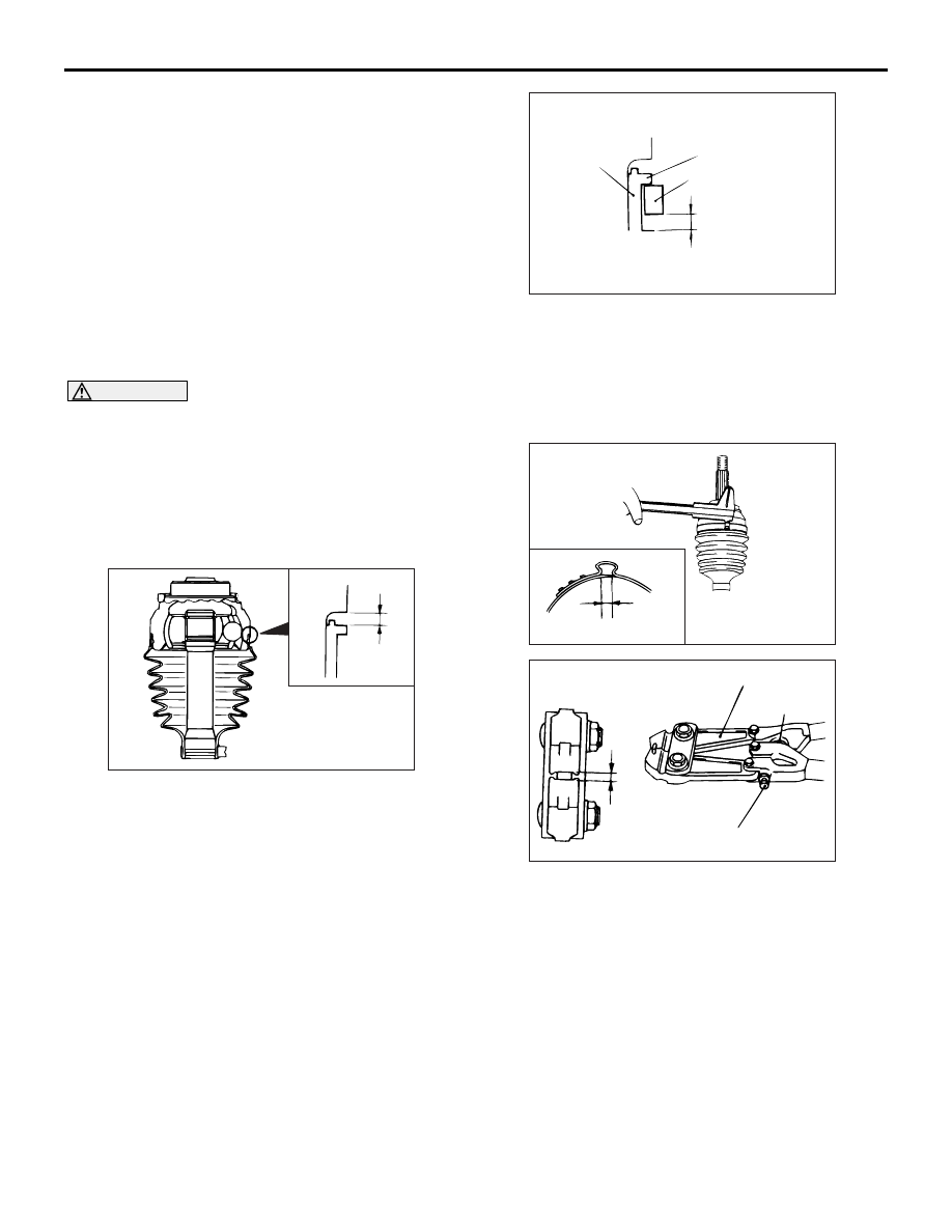
9. Install the BJ boot band (large) so that there is the 

clearance (C) between it and the BJ housing is at 
the standard value.

Standard value (C): 0.05 

 1.55 mm

10.Follow the same procedure as in step 3 to adjust 

the size of the opening (W) shown on special tool 
MB991561 so that it is at the standard value.

Standard value (W): 3.2 mm

AC001177

D

Projection

BJ boot band

BJ boot

AB

11.Place the BJ boot band (large) against the 

projection at the edge of the boot, and then 
secure it so that there is a clearance left as shown 
by (D) in the illustration.

12.Use special tool MB991561 to crimp the BJ boot 

band (large) in the same way as in step 5.

AC004720

E

AB

ACX00993AB

(W)

MB991561

Stopper

Adjusting bolt

13.Check that the crimping amount (E) of the BJ boot 

band is at the standard value.

Standard value (E): 2.4 

 2.8 mm

<If the crimping amount is larger than 2.8 mm>

Readjust the value of (W) in step 10 according 

to the following formula, and then repeat the 
operation in step 12.

W = 5.8 mm 

 E

Example: If E = 2.9 mm, then W = 2.9 mm.

 <If the crimping amount is smaller than 2.4 

mm>

Remove the BJ boot band, readjust the value of 

(W) in step 10 according to the following for-
mula, and then repeat the operating in steps 
11 and 12 using a new BJ boot band.

INNER SHAFT ASSEMBLY <4WD>

FRONT AXLE

26-30

W = 5.8 mm 

 E

Example: If E = 2.3 mm, then W = 3.5mm.

14.Check that the BJ boot band is not protruding 

past the place where it has been installed. If so, 
remove it and repeat the operations in steps 11 to 
13 using a new BJ boot band.

INNER SHAFT ASSEMBLY <4WD>

REMOVAL AND INSTALLATION

M1261004000201

CAUTION

*:Indicates parts which should be temporarily tightened, and then fully tightened with the vehicle on 
the earth in the unladen condition.

Pre-removal and Post-installation Operation
• Under Cover Removal and Installation (Refer to GROUP 

51, Under Cover .)

• Gear Oil Draining and Supplying (Refer to 

P.26-11

.)

• Driveshaft <RH> Removal and Installation (Refer to 

P.26-

23

).

• Shock absorber assembly <RH> Removal and Installation 

(Refer to GROUP 33, Shock Absorber Assembly  .)

AC804444

AC500641

4

N

90 ± 10 N·m*

1

2

3

4

5

6

7

8

9

10

11

12

N

105 ± 15 N·m

25 ± 5 N·m

N

17 ± 3 N·m

12 ± 2 N·m

90 ± 10 N·m

AB

Removal steps 

1.  Bolt


<<

A

>>

>>B<<

2.  Inner shaft assembly


3.  Circlip


 >>A<<

4.  Dust seal


5.  Pin <Except for Russia>


6.  Collar <Except for Russia>

Removal steps (Continued)

INNER SHAFT ASSEMBLY <4WD>

FRONT AXLE

26-31

REMOVAL SERVICE POINT

<<A>> INNER SHAFT ASSEMBLY REMOVAL

CAUTION

When pulling the inner shaft out from the front 
differential carrier, be careful that the spline part 
of the inner shaft does not damage the oil seal.

ACX00999 AC

MB990211

MB990906

Pull the inner shaft from the differential carrier by 
using the following special tools.

• driveshaft attachment (MB990906)

• Sliding hammer (MB990211)

INSTALLATION SERVICE POINTS

>>A<< DUST SEAL INSTALLATION

ACX01014 AB

MB990955

MB990938

Press-fit the new dust seal into the housing tube by 
using the following special tools, until it is flush with 
the housing tube end face.

• Installer bar (MB990938)

• Oil seal installer (MB990955)

>>B<< INNER SHAFT ASSEMBLY INSTALLATION

CAUTION

Be careful not to damage the lip of the dust seal 
and oil seal.

 DISASSEMBLY AND REASSEMBLY

M1261004200131

AC804403

1

2

3

N

AB


Disassembly steps 

<<

A

>> >>

B

<< 1. 

Bearing


>>

A

<< 2. 

Dust cover


3.

Inner shaft


7.  Actuator assembly <Except for 

Russia>


8.

Free wheel engage switch 
assembly <Except for Russia>

Support the differential with a 
transmission jack

9.

Gasket <Except for Russia>

10. Differential mounting bracket <RH>
11. Breather hose
12. Breather pipe

Removal steps (Continued)


Disassembly steps (Continued)

INNER SHAFT ASSEMBLY <4WD>

FRONT AXLE

26-32

DISASSEMBLY SERVICE POINT

<<A>> BEARING REMOVAL

ACX01002AB

1. Bend the outside periphery of dust cover inward 

with a wooden hammer.

ACX01003 AB

A

MB990560

2. After special tool bearing remover (MB990560) 

has been installed as shown, tighten the nut of the 
special tool until the portion of the special tool 
touches the bearing outer race.

ACX01013 AB

MB990560

3. Press out the inner shaft from the bearing.

REASSEMBLY SERVICE POINTS

>>A<< DUST COVER INSTALLATION

ACX01015 AB

Steel pipe

Using a steel pipe, install a new dust cover onto the 
inner shaft.

Steel pipe

mm

Overall length

50

Outside diameter

75

Wall thickness

4

>>B<< BEARING INSTALLATION

ACX01016AB

MB990560

Use special tool bearing remover (MB990560) to 
press-fit the bearing onto the inner shaft.


Content   ..  379  380  381  382   ..