Mitsubishi L200. Manual - part 378
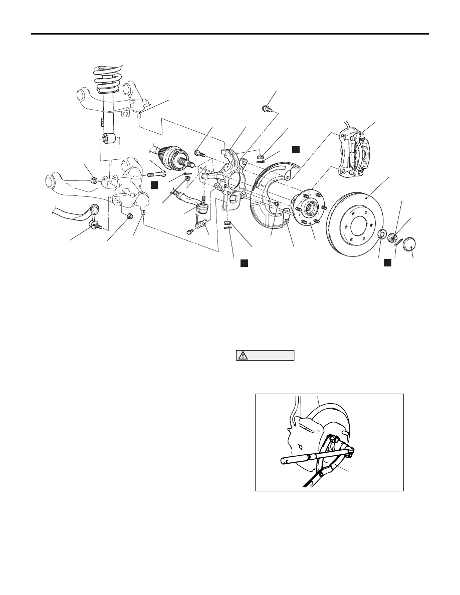
FRONT AXLE HUB ASSEMBLY
FRONT AXLE
26-17
<4WD>
AC500386
AC500367
N
N
N
5
4
3
1
8
9
2
7
6
74 ± 14 N·m
113 ± 9 N·m
147 ± 29 N·m
190 - 210 N·m
40 ± 4 N·m
AE
14
108 ± 10 N·m
12
11
10
16
N
13
15
9 ± 2 N·m
88 ± 10 N·m
17
18
105 ± 10 N·m*
Removal steps
1. Front wheel speed sensor <Vehicles
with ABS>
<<
A
>>
2. Caliper assembly
3. Brake disc
4. Hub cap
5. Split pin
<<
B
>> >>
A
<< 6. Driveshaft nut
>>
A
<< 7. Washer
8. Stabilizer link assembly to lower arm
connection
9. Shock absorber mounting bolt
10. Split pin
<<
C
>>
11. Tie rod end connection
12. Split pin
<<
C
>>
13. Lower arm ball joint connection
14. Split pin
<<
C
>>
15. Upper arm ball joint connection
16. Dust cover
17. Front hub assembly
<<D>>
18. Knuckle
REMOVAL SERVICE POINTS
<<A>> CALIPER ASSEMBLY REMOVAL
1. Remove the caliper assembly with brake hose.
2. Secure the removed caliper assembly with a wire
or other similar material at a position where it will
not interfere with the removal and installation of
the hub assembly and knuckle.
<<B>> FRONT HUB NUT/DRIVESHAFT NUT
REMOVAL
CAUTION
Do not apply pressure to wheel bearing by the
vehicle weight to avoid possible damage when
driveshaft nut is loosened.
AC102462
AC
MB990767
Use special tool front hub and flange yoke holder
(MB990767) to fix the hub and remove the front hub
nut or driveshaft nut.