Mitsubishi L200. Manual - part 365


  Index      Mitsubishi     Mitsubishi L200 - service repair manual 2012 year


Search            


Content   ..  363  364  365  366   ..


Mitsubishi L200. Manual - part 365


TRANSFER

AUTOMATIC TRANSMISSION OVERHAUL <V5A5>

23D-75

TRANSFER

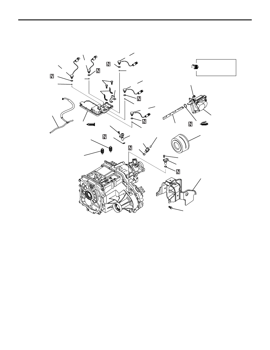
DISASSEMBLY AND REASSEMBLY

M1233006700674

AK602084AC

2

3

4

5

6

7

8

9

10

11

12

13

14

15

16

19

20

21

22

23

24

25

26

27

28

35 ± 6 N·m

35 ± 6 N·m

35 ± 6 N·m

35 ± 6 N·m

11 ± 1 N·m

35 ± 6 N·m

35 ± 6 N·m

1

11 ± 1 N·m

11 ± 1 N·m

11 ± 1 N·m

29

30

31

32

17

18

19 ± 3 N·m

Apply gear oil to
all moving parts
before installation.

Removal steps 

1.

Vacuum hose

>>X<<

2.

4LLC switch

3.

Gasket

4.

Steel ball

>>X<<

5.

2WD switch

6.

Gasket

7.

Steel ball

>>X<<

8.

Center differential lock switch

9.

Gasket

10. Steel ball

>>X<<

11. 4H switch
12. Gasket
13. Steel ball

>>X<<

14. 2WD/4WD switch
15. Gasket
16. Steel ball

17. Clip
18. Harness bracket

>>W<<

19. Transfer case cover

>>V<<

20. Shift rail drive gear

>>V<<

21. Shift rail drive gear
22. Dust seal guard
23. Dynamic damper
24. Vehicle speed sensor
25. O-ring
26. Rear output sensor
27. O-ring
28. Front output sensor
29. O-ring

>>U<<

30. Shift actuator
31. O-ring

>>U<<

32. Main shaft rail

Removal steps (Continued)

AK602085

33

34

35

36

37

38

39

40

41

42

43

44

46

47

48

49

50

51

52

53

64

65

66

67

68

69

54

55

56

57

58

59

60

61

62

63

35 ± 6 N·m

35 ± 6 N·m

5.0 ± 1.0 N·m

70

71

72

73

AC

45

21 ± 4 N·m

Apply gear oil to
all moving parts
before installation.

Removal steps 

>>T<<

33. Rear cover

>>S<<

34. Oil seal
35. Snap ring
36. Sensor rotor
37. Steel ball

>>R<<

38. Oil guide

>>Q<<

39. Spacer
40. Snap ring

>>P<<

41. Snap ring
42. Transmission wiring harness 

protector

43. Connector bracket
44. Connector bracket
45. Connector bracket
46. Clip
47. Connector bracket

>>O<<

48. Chain cover

>>N<<

49. Rear output shaft
50. O-ring
51. Needle bearing
52. Snap ring

53. Center differential planetary 

carrier

54. Viscous coupling

<<A>>

>>M<<

55. Chain

<<A>>

>>M<<

56. Front output shaft

>>M<<

57. Drive sprocket
58. Needle bearing

>>L<<

59. Synchronizer inner ring

>>L<<

60. Synchronizer inner cone

>>L<<

61. Synchronizer outer ring
62. Synchronizer inner spring

>>K<<

63. Snap ring

>>K<<

64. 2-4WD clutch

<<A>>

>>K<<

65. Sun gear
66. Needle bearing
67. Wave spring

>>J<<

68. 2-4WD clutch sleeve

>>J<<

69. 2-4WD shift fork

>>I<<

70. Spacer

>>I<<

71. Steel ball

>>H<<

72. Snap ring
73. Differential lock hub

TRANSFER

AUTOMATIC TRANSMISSION OVERHAUL <V5A5>

23D-76

Removal steps (Continued)

AK602086

19 ± 2 N·m

35 ± 6 N·m

35 ± 6 N·m

74

75

76

77

78

80

79

81

82

83

84

85

86

87

88

89

90

91

AC

Apply gear oil to
all moving parts
before installation.

Removal steps 

74. Harness bracket

>>G<<

75. Transfer case plate
76. Needle bearing
77. Countershaft gear

>>F<<

78. Spacer

>>E<<

79. H-L shift fork

>>E<<

80. H-L clutch sleeve

>>D<<

81. Snap ring
82. H-L clutch hub

83. Low speed gear
84. Needle bearing

>>C<<

85. Rear bearing retainer
86. Transfer drive shaft
87. Dust seal guard

>>B<<

88. Oil seal

<<B>>

>>A<<

89. Oil pool cover
90. Oil guide
91. Transfer case

TRANSFER

AUTOMATIC TRANSMISSION OVERHAUL <V5A5>

23D-77

Removal steps (Continued)

TRANSFER

AUTOMATIC TRANSMISSION OVERHAUL <V5A5>

23D-78

DISASSEMBLY SERVICE POINTS

<<A>> CHAIN / FORNT OUTPUT SHAFT / SUN GEAR REMOVAL

AK602087

Remove the chain, front output shaft and sun gear as 
a set from the transfer case.

<<B>> OIL POOL COVER REMOVAL

CAUTION

The oil pool cover normally does not require dis-
assembly. Once it is removed, the transfer case 
cannot be reused.

AK602088AC

Unstake the positions shown in the illustration to 
remove the oil pool cover.

ADJUSTMENT BEFORE REASSEMBLY

Spacer selection for adjustment of countershaft gear 
end play. (Refer to adjustment of transfer - spacer 
selection for adjustment of countershaft gear end 
play 

P.23D-84

)

RESASSEMBLY SERVICE POINTS

>>A<< OIL POOL COVER INSTALLATION

AK602089AC

5 mm

1.9 mm

Install the oil pool cover on a new transfer case. 
Stake the projecting portions of the transfer so that 
the dimensions will be as illustrated.

>>B<< OIL SEAL INSTALLATION

AK602090AC

MB990938

MB990932

1. Use special tools to install the oil seal.

• Handle (MB990938)

• Installer adapter (MB990932)

2. Apply the specified grease to the lip of oil seal.

Specified lubricant:
Mitsubishi Part No. 0101011 or equivalent

>>C<< SEAL BOLT INSTALLATION

AK602091AC

1. Apply the specified sealant to the threads.

Specified sealant:
3M STUD locking No. 4170 or equivalent


Content   ..  363  364  365  366   ..