Mitsubishi L200. Manual - part 217


  Index      Mitsubishi     Mitsubishi L200 - service repair manual 2012 year


Search            


Content   ..  215  216  217  218   ..


Mitsubishi L200. Manual - part 217


EXHAUST MANIFOLD AND TURBOCHARGER

INTAKE AND EXHAUST

15-23

Position the projection as shown in the illustration.

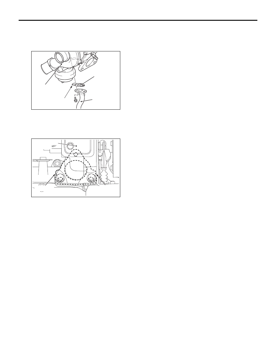
>>C<< OIL RETURN PIPE GASKET 
INSTALLATION

AC805772 AB

Projection

Oil return
pipe gasket

Turbocharger
assembly

Oil return pipe

Position the projection as shown in the illustration.

>>D<< TURBOCHARGER GASKET 
INSTALLATION

AC805775

AB

Projection

Projection

Turbocharger
assembly

Position the projection as shown in the illustration.

INSPECTION

M1151009400057

Check the following points; replace the part if a prob-
lem is found.
EXHAUST MANIFOLD CHECK
1. Check for damage or cracking of any part.
2. Using a straight edge and a feeler gauge, check 

for distortion of the cylinder head installation 
surface.
Standard value: 0.15 mm or less 
Limit: 0.20 mm

TURBOCHARGER ASSEMBLY CHECK
1. Visually check the turbine wheel and the 

compressor wheel for cracking or other damage.

2. Check whether the turbine wheel and the 

compressor wheel can be easily turned by hand.

3. Check for oil leakage from the turbocharger 

assembly.

4. Check whether or not the turbocharger waste gate 

regulating valve remains open. If any problem is 
found, replace the part after disassembly.

OIL PIPE AND OIL RETURN PIPE CHECK
Check the oil pipe and oil return pipe for clogging, 
bending or other damage. If there is clogging, clean 
it.

EXHAUST PIPE AND MAIN MUFFLER

INTAKE AND EXHAUST

15-24

EXHAUST PIPE AND MAIN MUFFLER

REMOVAL AND INSTALLATION

M1151008600586

<Except Euro5>

Pre-removal Operation
• Under Skid Plate and Engine Room Under Cover 

Removal (Refer to GROUP 51 

− Under Cover ).

Post-installation Operation
• Under Skid Plate and Engine Room Under Cover Installa-

tion (Refer to GROUP 51 

− Under Cover ).

ACB00721

25 ± 4 N·m

6

4

AB

5

N

3

1

7

25 ± 4 N·m

49 ± 5 N·m

N

57 ± 7 N·m

2

N

Removal steps 

1.

Front exhaust pipe

2.

Exhaust pipe gasket

3.

Seal ring

4.

Centre exhaust pipe

5.

Exhaust pipe gasket

6.

Exhaust main muffler

7.

Dash heat protector panel

Removal steps (Continued)

EXHAUST PIPE AND MAIN MUFFLER

INTAKE AND EXHAUST

15-25

<Euro5>

CAUTION

When the DPF is replaced, use the M.U.T.-III to initialise the learning value (Refer to GROUP 00 

 Pre-

cautions before Service, Initialisation Procedure for Learning Value in DPF System ).

Pre-removal Operation
• Under Skid Plate and Engine Room Under Cover 

Removal (Refer to GROUP 51 

− Under Cover ).

Post-installation Operation
• Under Skid Plate and Engine Room Under Cover Installa-

tion (Refer to GROUP 51 

− Under Cover ).

ACB00722

25 ± 4 N·m

9

4

AB

8

N

3

1

10

25 ± 4 N·m

49 ± 5 N·m

N

57 ± 7 N·m

2

N

8.0 ± 2.0 N·m

8.0 ± 2.0 N·m

4

36 ± 4 N·m

36 ± 4 N·m

6

6

7

5

Removal steps 

No.2 exhaust gas temperature 
sensor (Refer to GROUP 17 

− 

Emission Control, DPF System 
Sensors )

1.

Front exhaust pipe

2.

Exhaust pipe gasket

3.

Seal ring

No.2 crossmember (Refer to 
GROUP 32 

− Rear Engine 

Mounting ) <2WD>

No.3 exhaust gas temperature 
sensor (Refer to GROUP 17 

− 

Emission Control, DPF System 
Sensors )

4.

Exhaust pressure hose connection

5.

Exhaust pressure pipe and DPF 
assembly

6.

Exhaust pressure pipe

7.

DPF

8.

Exhaust pipe gasket

9.

Exhaust main muffler

10. Front floor heat protector panel

Removal steps (Continued)

16-1

GROUP 16

ENGINE 

ELECTRICAL

CONTENTS

CHARGING SYSTEM  . . . . . . . . . . . .

16-2

GENERAL INFORMATION. . . . . . . . . . . . . 

16-2

SERVICE SPECIFICATION(S) . . . . . . . . . . 

16-4

SPECIAL TOOL(S) . . . . . . . . . . . . . . . . . . . 

16-5

ON-VEHICLE SERVICE . . . . . . . . . . . . . . . 

16-6

ALTERNATOR OUTPUT LINE VOLTAGE DROP 
TEST . . . . . . . . . . . . . . . . . . . . . . . . . . . . . . 

16-6

OUTPUT CURRENT TEST. . . . . . . . . . . . . 

16-7

REGULATED VOLTAGE TEST  . . . . . . . . . 

16-9

WAVE PATTERN CHECK USING AN 
OSCILLOSCOPE  . . . . . . . . . . . . . . . . . . . . 

16-10

ALTERNATOR ASSEMBLY . . . . . . . . . . . . 

16-13

ALTERNATOR ASSEMBLY REMOVAL AND 
INSTALLATION. . . . . . . . . . . . . . . . . . . . . . 

16-13

STARTING SYSTEM . . . . . . . . . . . . .

16-14

GENERAL INFORMATION. . . . . . . . . . . . . 

16-14

SERVICE SPECIFICATION(S) . . . . . . . . . . 

16-15

ON-VEHICLE SERVICE . . . . . . . . . . . . . . . 

16-16

STARTER RELAY CONTINUITY CHECK  . 

16-16

STARTER MOTOR ASSEMBLY. . . . . . . . . 

16-16

STARTER MOTOR ASSEMBLY REMOVAL AND 
INSTALLATION. . . . . . . . . . . . . . . . . . . . . . 

16-16

STARTER MOTOR ASSEMBLY INSPECTION


 . . . . . . . . . . . . . . . . . . . . . . . . . . . . . . . . . . . . . .

16-17

GLOW SYSTEM . . . . . . . . . . . . . . . . .

16-18

GENERAL INFORMATION . . . . . . . . . . . . . 

16-18

SERVICE SPECIFICATION(S) . . . . . . . . . . 

16-21

ON-VEHICLE SERVICE . . . . . . . . . . . . . . . 

16-22

GLOW PLUG CHECK <Euro5>  . . . . . . . . . 

16-22

SELF-REGULATING GLOW SYSTEM CHECK 
<Except Euro5>. . . . . . . . . . . . . . . . . . . . . . 

16-22

CHECK THE ENGINE ECU TERMINALS <Euro5>


. . . . . . . . . . . . . . . . . . . . . . . . . . . . . . . . . . . . . . 

16-23

CHECK THE ENGINE ECU TERMINALS <Except 
Euro5> . . . . . . . . . . . . . . . . . . . . . . . . . . . . . 

16-23

GLOW PLUG RELAY CHECK <Except Euro5>


. . . . . . . . . . . . . . . . . . . . . . . . . . . . . . . . . . . . . . 

16-23

GLOW PLUG CHECK <Except Euro5>  . . . 

16-24

ENGINE COOLANT TEMPERATURE SENSOR 
CHECK <Except Euro5> . . . . . . . . . . . . . . . 

16-24

GLOW PLUG. . . . . . . . . . . . . . . . . . . . . . . . 

16-25

GLOW PLUG REMOVAL AND INSTALLATION


. . . . . . . . . . . . . . . . . . . . . . . . . . . . . . . . . . . . . . 

16-25

GLOW PLUG RELAY <Except Euro5> . . . . 

16-25

GLOW PLUG RELAY REMOVAL AND INSTALLATION


. . . . . . . . . . . . . . . . . . . . . . . . . . . . . . . . . . . . . . 

16-25

GLOW CONTROL UNIT <Euro5> . . . . . . . . 

16-26

GLOW CONTROL UNIT REMOVAL AND 
INSTALLATION . . . . . . . . . . . . . . . . . . . . . . 

16-26


Content   ..  215  216  217  218   ..