Mitsubishi L200. Manual - part 87


  Index      Mitsubishi     Mitsubishi L200 - service repair manual 2012 year


Search            


Content   ..  85  86  87  88   ..


Mitsubishi L200. Manual - part 87


TROUBLESHOOTING

DIESEL FUEL

13A-144

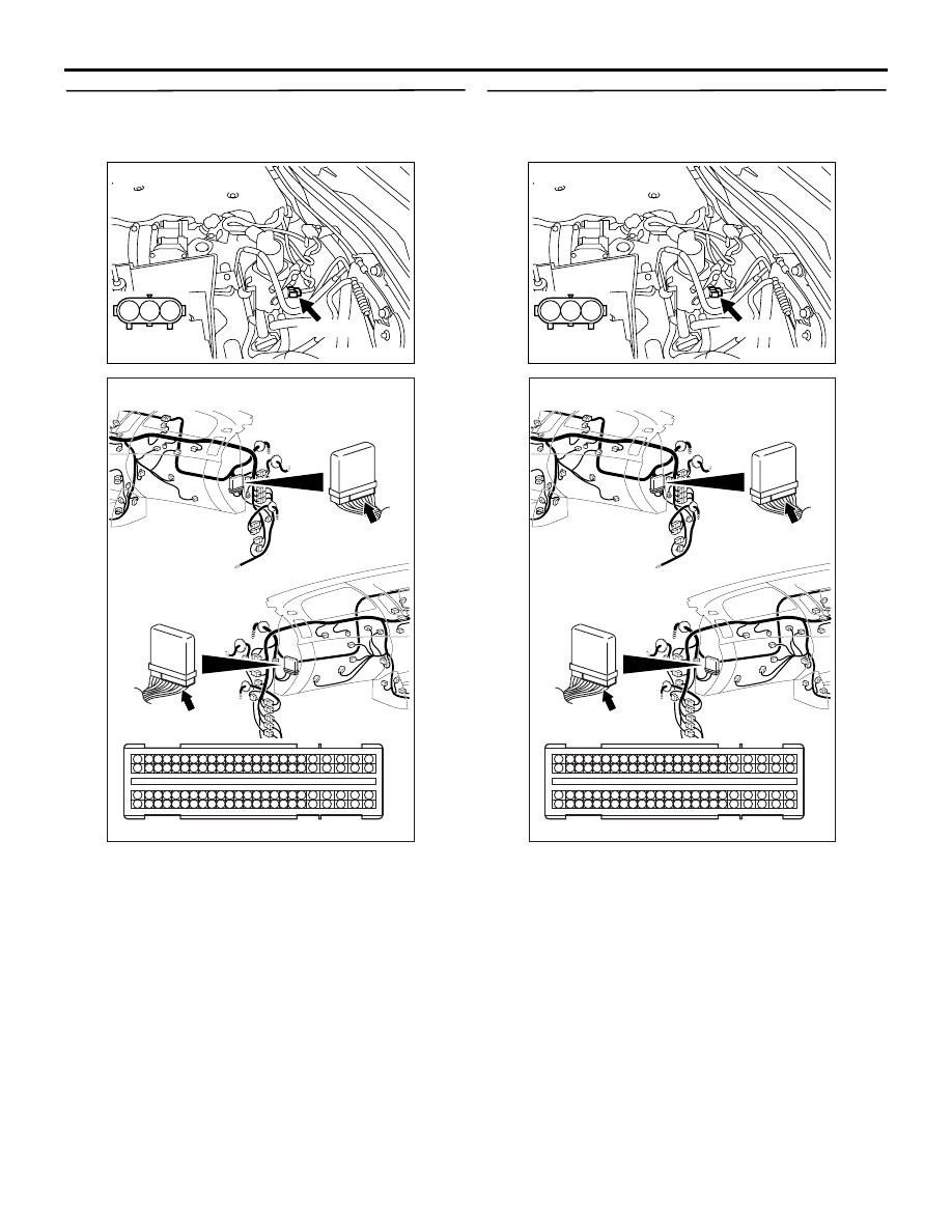
STEP 5. Check harness between A-44 (terminal 
No. 1) rail pressure sensor connector and C-105 
(terminal No. 70) engine-ECU connector.

NOTE: Before checking harness, check intermediate 
connector A-131, and repair if necessary.

• Check power supply line for damage.

Q: Is the check result normal?

YES : 

Go to Step 6.

NO : 

Repair the damaged harness wire.

STEP 6. Check harness between A-44 (terminal 
No. 2) rail pressure sensor connector and C-105 
(terminal No. 64) engine-ECU connector.

NOTE: Before checking harness, check intermediate 
connector A-131, and repair if necessary.

• Check output line for damage.

Q: Is the check result normal?

YES : 

Go to Step 7.

NO : 

Repair the damaged harness wire.

AK501327

1

2

3

AB

A-44 (B)

Harness side 
connector

Connector: A-44

AKA00089

1

2

3

4

5

6

7

8

9

10

11

12

13

14

15

16

17

18

19

20

21

22

23

24

25

26

27

28

29

30

31

32

33

34

35

36

37

38

39

40

41

42

49

50

51

52

53

54

55

56

57

58

59

60

61

62

63

64

65

66

67

68

69

70

71

72

43

44

45

46

47

48

73

74

75

76

77

78

79

80

81

82

83

84

85

86

87

88

89

90

91

92

93

94

95

96

C-105 (B)

C-105 (B)

<R.H. drive vehicles>

Harness side connector

<L.H. drive vehicles>

Connector: C-105

AB

TROUBLESHOOTING

DIESEL FUEL

13A-145

STEP 7. Perform voltage measurement at A-44 
rail pressure sensor connector.

• Use special tool test harness (MB991658) to con-

nect connector, and measure at pick-up harness.

• Engine: Idling (after warning up)

• Voltage between terminal No. 2 and earth.

OK: 1.15 

 1.75 V

Q: Is the check result normal?

YES : 

Replace the engine-ECU. When the engine-

ECU is replaced, write the chassis number 
(Refer to GROUP 00 

− Precautions Before 

Service 

− How to Perform Chassis Number 

Writing ). After replacing the engine-ECU, 
register the injector identification code and 
learn fuel injection (Refer to GROUP 00 

− 

Precautions Before Service 

− What The 

Common Rail Engine Learns ). After 
registering the injector identification code, 
the vehicle equipped with the DPF carries 
out the forcible DPF regeneration. (Refer to 
GROUP 17 

− Emission Control − Diesel 

Particulate Filter (DPF) System 

− Forcible 

DPF Regeneration ).

NO : 

Replace the common rail assembly and fuel 
injection tubes.

AK501327

1

2

3

AB

A-44 (B)

Harness side 
connector

Connector: A-44

TROUBLESHOOTING

DIESEL FUEL

13A-146

Code No. P0192: Rail Pressure Sensor Circuit Low Input

OPERATION

• A power voltage of 5 V is applied to the rail pres-

sure sensor power terminal (terminal No. 1) from 
the engine-ECU (terminal No. 70) and earthed to 
the engine-ECU (terminal No. 88) from the rail 
pressure sensor (terminal No. 3).

• The sensor signal is inputted to the engine-ECU 

(terminal No. 64) from the rail pressure sensor 
output terminal (terminal No. 2).

FUNCTION

• The rail pressure sensor converts the rail pres-

sure into a voltage signal and inputs the signal to 
the engine-ECU.

• In response to the signal, the engine-ECU cor-

rects the fuel injection quantity.

TROUBLE JUDGMENT

Check Conditions

• Battery positive voltage is 8 − 16 V

• 2 seconds later after the ignition switch has been 

in "ON" position or the engine has started up.

Judgment Criterion

• The rail pressure sensor output voltage is 0.70 V 

or less for 0.5 second.

PROBABLE CAUSES

• Failed rail pressure sensor

• Open/short circuit or harness damage in rail pres-

sure sensor circuit or loose connector contact

• Failed engine-ECU

AKA00196

1

2

3

1

2

3

4

5 6 7 8 9

10 1112 13 14 15 16 17 18 19 20 21 22 23 24

25 26

27 28 29 30 31 32 33 34 35 36 37 38 39 40 41 42

49 50 51 52 53 54 55 56 57 58 59 60 61 62 63 64 65 66 67 68 69 70 71 72

43 44 45 46 47 48

73 74 75 76 77 78 79 80 81 82 83 84 85 86 87 88 89 90 91 92 93 94 95 96

Engine-ECU

W

R

B

W

R

B

B

A-44

(MU802408)

Rail pressure
sensor

2

1

3

5

6

4

A-131

64

70

88

Rail Pressure Sensor Circuit

AD

Wire colour code
B: Black  LG: Light green  G: Green  L: Blue  W: White  Y: Yellow  SB: Sky blue  BR: Brown  O: Orange  GR: Grey
R: Red  P: Pink  V:Violet  PU: Purple  SI: Silver

C-105

5 V

TROUBLESHOOTING

DIESEL FUEL

13A-147

DIAGNOSIS PROCEDURE

STEP 1. M.U.T.-III data list

• Refer to Data List Reference Table 

P.13A-542

.

a. Item 63: Rail pressure sensor

Q: Is the check result normal?

YES : 

Intermittent malfunction (Refer to GROUP 

00 

− How to Use Troubleshooting/

Inspection Service Points 

− How to Cope 

with Intermittent Malfunctions ).

NO : 

Go to Step 2 .

STEP 2. Connector check: A-44 rail pressure 
sensor connector

Q: Is the check result normal?

YES : 

Go to Step 3 .

NO : 

Repair or replace the connector.

STEP 3. Perform voltage measurement at A-44 
rail pressure sensor connector.

• Use special tool test harness (MB991658) to con-

nect connector, and measure at pick-up harness.

• Ignition switch: ON

• Voltage between terminal No. 1 and earth.

OK: 4.9 

 5.1 V

Q: Is the check result normal?

YES : 

Go to Step 9 . 

NO : 

Go to Step 4 

STEP 4. Perform voltage measurement at C-105 
engine-ECU connector.

• Measure engine-ECU terminal voltage.

• Ignition switch: ON

• Voltage between terminal No. 70 and earth.

OK: 4.9 

 5.1 V

Q: Is the check result normal?

YES : 

Go to Step 8 .

NO : 

Go to Step 5 .

AK501327

1

2

3

AB

A-44 (B)

Harness side 
connector

Connector: A-44

AK501327

1

2

3

AB

A-44 (B)

Harness side 
connector

Connector: A-44

AKA00089

1

2

3

4

5

6

7

8

9

10

11

12

13

14

15

16

17

18

19

20

21

22

23

24

25

26

27

28

29

30

31

32

33

34

35

36

37

38

39

40

41

42

49

50

51

52

53

54

55

56

57

58

59

60

61

62

63

64

65

66

67

68

69

70

71

72

43

44

45

46

47

48

73

74

75

76

77

78

79

80

81

82

83

84

85

86

87

88

89

90

91

92

93

94

95

96

C-105 (B)

C-105 (B)

<R.H. drive vehicles>

Harness side connector

<L.H. drive vehicles>

Connector: C-105

AB


Content   ..  85  86  87  88   ..