Mazda Transaxle A65M–R. Manual - part 3


  Index      Mazda     Mazda Transaxle A65M–R - service manual 2002 year


Search            


Content   ..  1  2  3  4  ..


Mazda Transaxle A65M–R. Manual - part 3


FUNDAMENTAL PROCEDURES 

GI–7

GI

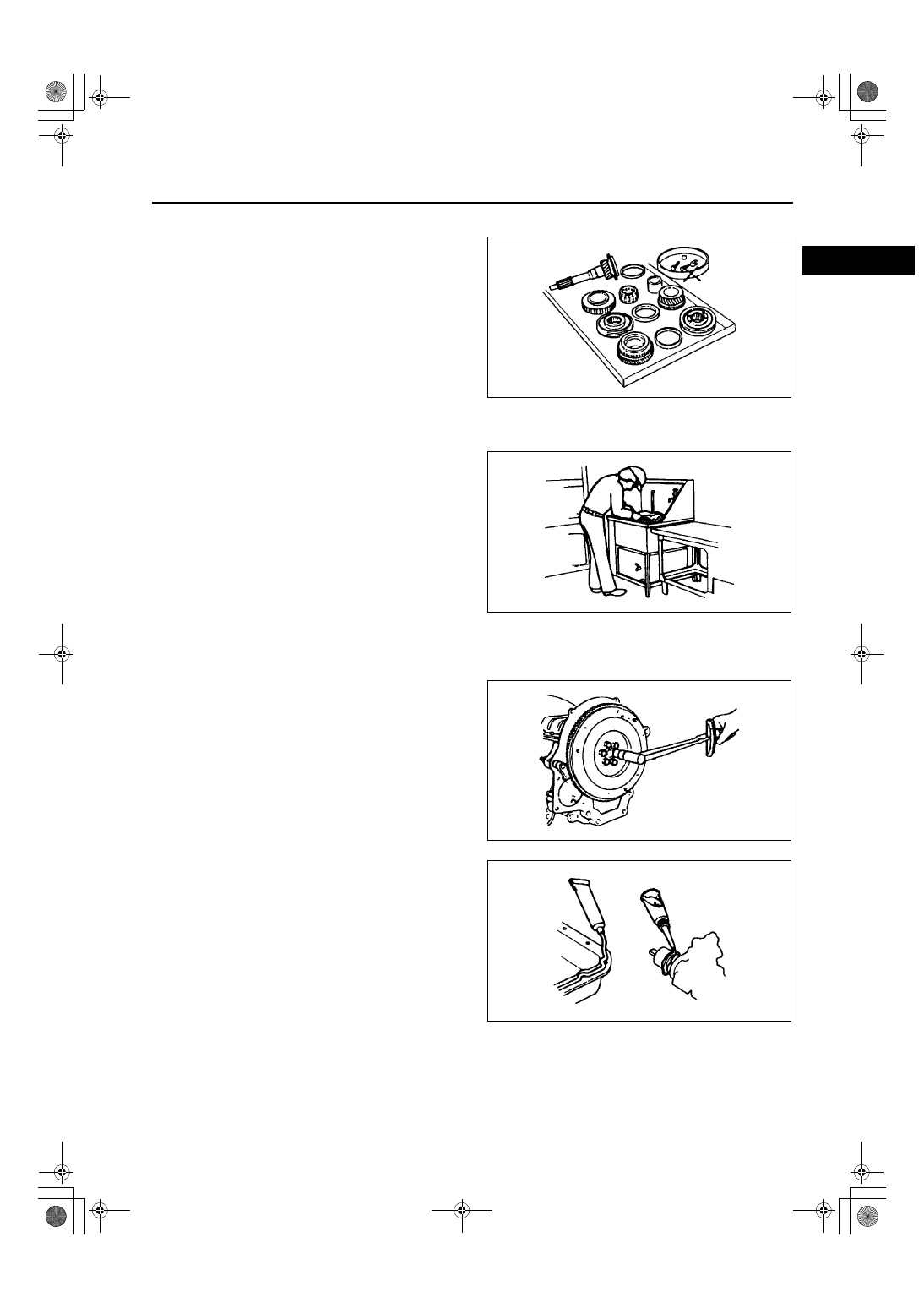
ARRANGEMENT OF PARTS

AME201400004M05

All disassembled parts should be carefully 
arranged for reassembly.

Be sure to separate or otherwise identify the parts 
to be replaced from those that will be reused.

End Of Sie

CLEANING OF PARTS

AME201400004M06

All parts to be reused should be carefully and 
thoroughly cleaned in the appropriate method.

Warning

••••

Using compressed air can cause dirt and 
other particles to fly out causing injury to 
the eyes. Wear protective eye wear 
whenever using compressed air.

End Of Sie

REASSEMBLY

AME201400004M07

Standard values, such as torques and certain 
adjustments, must be strictly observed in the 
reassembly of all parts.

If removed, these parts should be replaced with 
new ones:
— Oil seals
— Gaskets
— O-rings
— Lockwashers
— Cotter pins
— Nylon nuts

Depending on location:
— Sealant and gaskets, or both, should be 

applied to specified locations. When sealant 
is applied, parts should be installed before 
sealant hardens to prevent leakage.

— Oil should be applied to the moving 

components of parts.

— Specified oil or grease should be applied at 

the prescribed locations (such as oil seals) 
before reassembly.

End Of Sie

WGIWXX0029E

WGIWXX0030E

WGIWXX0031E

WGIWXX0032E

GI–8

FUNDAMENTAL PROCEDURES 

ADJUSTMENT

AME201400004M08

Use suitable gauges and/or testers when making 
adjustments.

End Of Sie

RUBBER PARTS AND TUBING

AME201400004M09

Prevent gasoline or oil from getting on rubber 
parts or tubing.

End Of Sie

HOSE CLAMPS

AME201400004M10

When reinstalling, position the hose clamp in the 
original location on the hose and squeeze the 
clamp lightly with large pliers to ensure a good fit.

End Of Sie

TORQUE FORMULAS

AME201400004M11

When using a torque wrench-SST or equivalent 
combination, the written torque must be 
recalculated due to the extra length that the SST 
or equivalent adds to the torque wrench. 
Recalculate the torque using the following 
formulas. Choose the formula that applies to you.

A : The length of the SST past the torque wrench drive
L : The length of the torque wrench

End Of Sie

WGIWXX0033E

WGIWXX0034E

WGIWXX0035E

Torque Unit

Formula

N·m

N·m 

×

 [L/(L+A)]

kgf·m

kgf·m 

×

 [L/(L+A)]

kgf·cm

kgf·cm 

×

 [L/(L+A)]

ft·lbf

ft·lbf 

×

 [L/(L+A)]

in·lbf

in·lbf 

×

 [L/(L+A)]

WGIWXX0036E

FUNDAMENTAL PROCEDURES, ELECTRICAL SYSTEM 

GI–9

GI

VISE

AME201400004M12

When using a vise, put protective plates in the 
jaws of the vise to prevent damage to parts.

End Of Sie

CONNECTORS

AME201700006M01

Data Link Connector

Insert the probe into the service hole when 
connecting a jumper wire to the data link 
connector.

Caution

••••

Inserting a jumper wire probe into the 
data link connector terminal may damage 
the terminal.

Disconnecting Connectors

When disconnecting connector, grasp the 
connectors, not the wires.

Connectors can be disconnected by pressing or 
pulling the lock lever as shown.

WGIWXX0037E

ELECTRICAL SYSTEM

X3U000WAY

WGIWXX0041E

WGIWXX0042E

GI–10

ELECTRICAL SYSTEM 

Locking Connector

When locking connectors, listen for a click 
indicating they are securely locked.

Inspection

When a tester is used to inspect for continuity or 
measuring voltage, insert the tester probe from 
the wiring harness side.

Inspect the terminals of waterproof connectors 
from the connector side since they cannot be 
accessed from the wiring harness side.

Caution

••••

To prevent damage to the terminal, wrap 
a thin wire around the tester probe before 
inserting into terminal.

Terminals
Inspection

Pull lightly on individual wires to verify that they 
are secured in the terminal.

X3U000WB1

WGIWXX0044E

WGIWXX0045E

WGIWXX0064E


Content   ..  1  2  3  4  ..