Mazda CX 7. Manual - part 437
INSTRUMENTATION/DRIVER INFO.
09-22–17
09-22
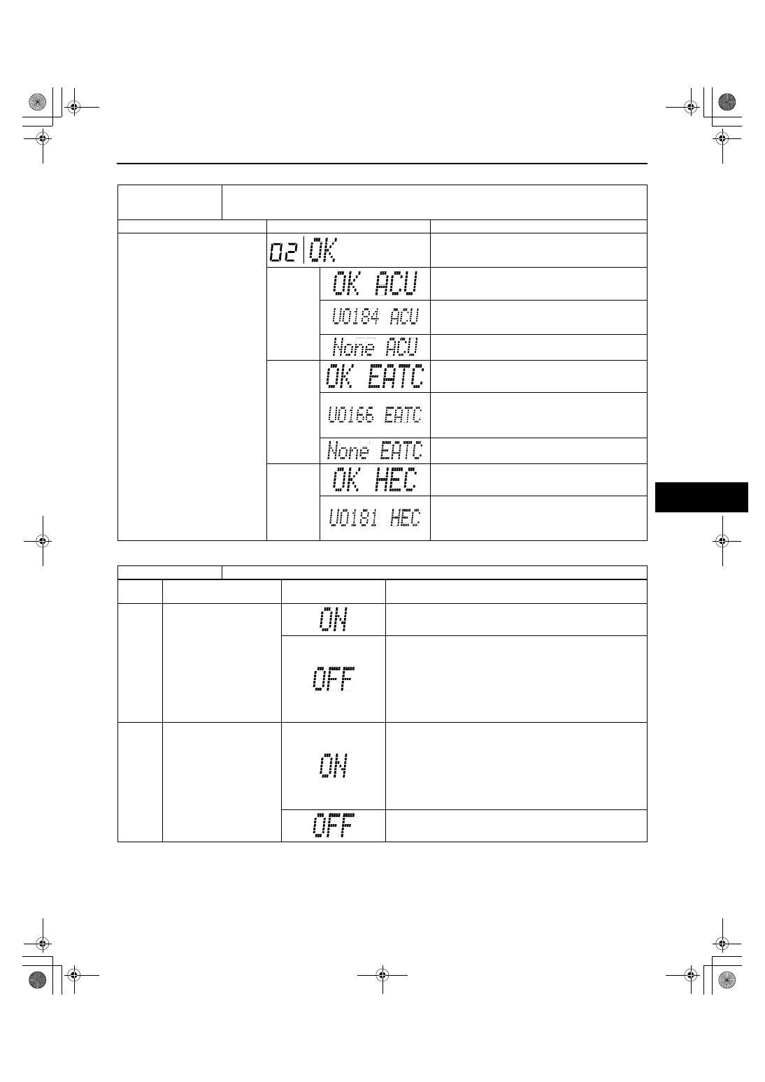
Check code 02
Check code 04
Check code 02
• Communication status to audio unit
• Communication status to climate control unit
• Communication status to instrument cluster
INSPECTION CONDITION
DISPLAY
ACTION
Select the check code 02.
(The diagnostic results will be
displayed once each in the order
of audio unit, heater control unit,
and instrument cluster.)
All communications are normal.
Audio unit
Communication to audio unit is normal.
Communication error to audio unit. (DTC U0184)
(See 09-02D-7 DTC TABLE[MULTIPLEX
COMMUNICATION SYSTEM])
Vehicle without audio unit.
Climate
control unit
Communication to climate control unit is normal.
Communication error to climate control unit. (DTC
U0166)
(See 09-02D-7 DTC TABLE[MULTIPLEX
COMMUNICATION SYSTEM])
Vehicle without climate control unit.
Instrument
cluster
Communication to instrument cluster is normal.
Communication error to instrument cluster. (DTC
U0181)
(See 09-02D-7 DTC TABLE[MULTIPLEX
COMMUNICATION SYSTEM])
Check code 04
TNS relay ON/OFF signal
STEP
INSPECTION
CONDITION
DISPLAY
ACTION
1
Turn the headlight switch
to the TNS position. (TNS
relay ON)
Go to the next step.
Verify that the voltage of information display terminal C is B+.
• If the voltage is as specified, replace the information
display.
• If the voltage is not as specified, inspect the following
parts:
— TNS relay
— Wiring harness (Battery— TNS relay— information
display)
2
Turn the headlight switch
off. (TNS relay OFF)
Verify that the voltage of the information display terminal C is
1.0 V or less.
• If the voltage is as specified, replace the information
display.
• If the voltage is not as specified, inspect the following
parts:
— TNS relay
— Wiring harness (TNS relay— information display)
Input signal to the information display is normal.
1871-1U-06B(09-22).fm 17 ページ 2006年3月15日 水曜日 午後12時56分