Mazda CX 7. Manual - part 419


  Index      Mazda     Mazda CX 7 - service repair manual 2007 year


Search            


Content   ..  417  418  419  420   ..


Mazda CX 7. Manual - part 419


LIGHTING SYSTEMS 

09-18–11

09-18

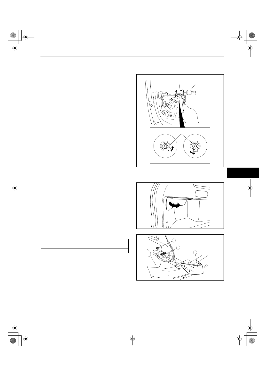
FRONT FOG LIGHT BULB REMOVAL/INSTALLATION

id091800802300

1. Disconnect the negative battery cable.
2. Slightly bend back the mudguard.
3. Disconnect the front fog light bulb connector and 

remove the front fog light bulb by turning it in the 
direction of the arrow.

Caution

• A halogen bulb generates extremely high 

heat when it is illuminated. If the surface 
of the bulb is soiled, excessive heat will 
build up and the life of the bulb will be 
shortened. When handling the bulb, hold 
the flange, not the glass.

4. Install in the reverse order of removal.

End Of Sie

WM: REAR COMBINATION LIGHT

REAR COMBINATION LIGHT REMOVAL/INSTALLATION

id091800801000

1. Disconnect the negative battery cable.
2. Remove the service hole cover.

3. Remove in the order indicated in the table.

.

4. Install in the reverse order of removal.

End Of Sie

CONNECTOR

FRONT FOG 
LIGHT BULB

LH

RH

FRONT FOG LIGHT BULB

acxuuw00001720

1

Connector

2

Nut

3

Rear combination light

acxuuw00001722

3

1

2

4.1—6.1 N·m 
{42—62 kgf·cm, 37—53 in·lbf}

acxuuw00001723

LIGHTING SYSTEMS 

09-18–12

REAR COMBINATION LIGHT BULB REMOVAL/INSTALLATION

id091800805900

1. Disconnect the negative battery cable.
2. Remove the service hole cover.

3. Remove in the order indicated in the table.

.

4. Install in the reverse order of removal.

End Of Sie

WM: HIGH-MOUNT BRAKE LIGHT

HIGH-MOUNT BRAKE LIGHT REMOVAL/INSTALLATION

id091800802000

1. Disconnect the negative battery cable.
2. Remove the cover in the interior of the liftgate.
3. Remove in the order indicated in the table.

.

4. Install in the reverse order of removal.

End Of Sie

WM: LICENSE PLATE LIGHT

LICENSE PLATE LIGHT REMOVAL/INSTALLATION

id091800801100

1. Disconnect the negative battery cable.
2. Remove the rear finisher.(See09-16-3 REAR FINISHER REMOVAL/INSTALLATION.)
3. Remove in the order indicated in the table.

.

4. Install in the reverse order of removal.

End Of Sie

WM: COMBINATION SWITCH

1

Connector

2

Socket

3

Rear side marker light bulb

4

Back-up light bulb

5

Rear turn light bulb

6

Brake light/taillight bulb 

acxuuw00001722

1

1

2

2

5

4

3

6

acxuuw00001724

1

Connector

2

High-mount brake light 

2

1

TAB

TAB

acxuuw00001726

1

Connector

2

License plate light 

3

Lens

4

License plate light  bulb

HOOK

4

3

1

2

acxuuw00001727

LIGHTING SYSTEMS 

09-18–13

09-18

COMBINATION SWITCH REMOVAL/INSTALLATION

id091800802500

Warning

• If the negative battery cable or the steering angle sensor connector is disconnected, the stored 

initial position of the steering angle sensor will be cleared and the DSC will not operate properly, 
making the vehicle unsafe to drive. Perform the steering angle sensor initialization procedure after 
connecting the negative battery cable. 

1. Disconnect the negative battery cable.
2. Remove the following parts: 

(1) Driver-side air bag module (See 08-10-6 DRIVER-SIDE AIR BAG MODULE REMOVAL/INSTALLATION.)
(2) Steering wheel (See 06-14-6 STEERING WHEEL AND COLUMN REMOVAL/INSTALLATION.)
(3) Column cover (See 09-17-8 COLUMN COVER REMOVAL/INSTALLATION.)

3. Remove in the order indicated in the table.

.

4. Disconnect the steering angle sensor connector.
5. Install in the reverse order of removal.
6. Perform the steering angle sensor reference point 

setting. (See 09-40-8 STEERING ANGLE 
SENSOR INITIALIZATION PROCEDURE.)

End Of Sie

COMBINATION SWITCH DISASSEMBLY/ASSEMBLY

id091800802600

Caution

• If the disc on the combination switch is deformed or has foreign material adhering to it, 

performance of the steering angle sensor may be reduced, causing abnormal operation. When 
handling the combination switch, be careful not to deform the disc and make sure there is no 
foreign material on it.

1. Disassemble in the order indicated in the table.

.

2. Assemble in the reverse order of disassembly.

End Of Sie

WM: LIGHT SWITCH

LIGHT SWITCH REMOVAL/INSTALLATION

id091800802800

1. Disconnect the negative battery cable.
2. Remove the column cover. (See 09-17-8 COLUMN COVER REMOVAL/INSTALLATION.)
3. Disconnect the light switch connector.
4. Remove the screws, then remove the light switch.
5. Install in the reverse order of removal.

End Of Sie

1

Connector

2

Screw

3

Combination switch

3

1

2

2

ampjjw00002214

1

Screw

2

Wiper and washer switch

3

Light  switch

4

Body

4

3

1

2

1

acxuuw00001728

CONNECTOR

SCREW

LIGHT SWITCH

acxuuw00001729

LIGHTING SYSTEMS 

09-18–14

LIGHT SWITCH INSPECTION

id091800802900

1. Verify that the continuity between the light switch terminals is as indicated in the table.

• If not as indicated in the table, replace the light switch.

Headlight switch (Vehicle without auto light)

Headlight switch (Vehicle with auto light)

Turn Switch

End Of Sie

WM: FRONT FOG LIGHT SWITCH

O

Q

C

E

A

P

L

J

F

D

*

*

*

*

*

*

*

L

P

J

Q

O

R

HI

FLASH-
TO-PASS

HEAD-
LIGHT

OFF

TNS

LO

acxuuw00001730

: Continuity 

Switch position

Light

Dimmer

Flash-

to-pass

OFF

Off

On

Off

On

Off

On

-

-

-

TNS

LO

HI

Head-

light

Terminal 

J

L

P

O

Q

R

acxuuw00001731

O

Q

C

E

A

P

L

J

F

H

D

*

*

*

*

*

*

L

P

J

H

Q

O

R

HI

FLASH-
TO-PASS

HEAD-
LIGHT

AUTO

OFF

TNS

LO

acxuuw00001732

: Continuity 

Switch position

Light

Dimmer

Flash-

to-pass

OFF

Off

On

Off

On

Off

On

-

-

-

TNS

LO

HI

Head-

light

Off

On

-

LO

HI

Auto

Terminal 

J

L

P

O

Q

R

H

acxuuw00001733

C

LEFT

RIGHT

E

A

O

Q

C

E

A

P

L

J

F

H

D

*

*

*

*

*

*

acxuuw00001734

: Continuity 

Switch position

Left

Off

Right

Terminal 

A

C

E

acxuuw00001735


Content   ..  417  418  419  420   ..