Mazda CX 7. Manual - part 348
ON-BOARD DIAGNOSTIC [AUDIO]
09-02G–1
09-02G
09-02G ON-BOARD DIAGNOSTIC [AUDIO]
STARTING PROCEDURE FOR
ON-BOARD DIAGNOSTIC
TEST MODE[AUDIO] . . . . . . . . . . . . . . 09-02G–1
SUPPLIER IDENTIFICATION
PROCEDURE[AUDIO] . . . . . . . . . . . . . 09-02G–2
Identification Using the Label or
Inscribed Lettering . . . . . . . . . . . . . . 09-02G–2
Identification Using the On-board
Diagnostic Test Mode. . . . . . . . . . . . . 09-02G–2
MEMORY CLEARING PROCEDURE
[AUDIO] . . . . . . . . . . . . . . . . . . . . . . . . . 09-02G–2
DTC TABLE[AUDIO] . . . . . . . . . . . . . . . . 09-02G–3
DTC 16:ER12[AUDIO] . . . . . . . . . . . . . . . 09-02G–4
DTC 17:ER11[AUDIO] . . . . . . . . . . . . . . . 09-02G–4
DIAGNOSTIC ASSIST FUNCTION
[AUDIO] . . . . . . . . . . . . . . . . . . . . . . . . . 09-02G–5
Structural View . . . . . . . . . . . . . . . . . . . 09-02G–5
Button Inspection . . . . . . . . . . . . . . . . . 09-02G–5
Speaker Inspection . . . . . . . . . . . . . . . . 09-02G–5
Radio Reception
Condition Inspection. . . . . . . . . . . . . . 09-02G–6
Antenna control
condition inspection. . . . . . . . . . . . . . . 09-02G–6
End of Toc
WM: AUDIO UNIT
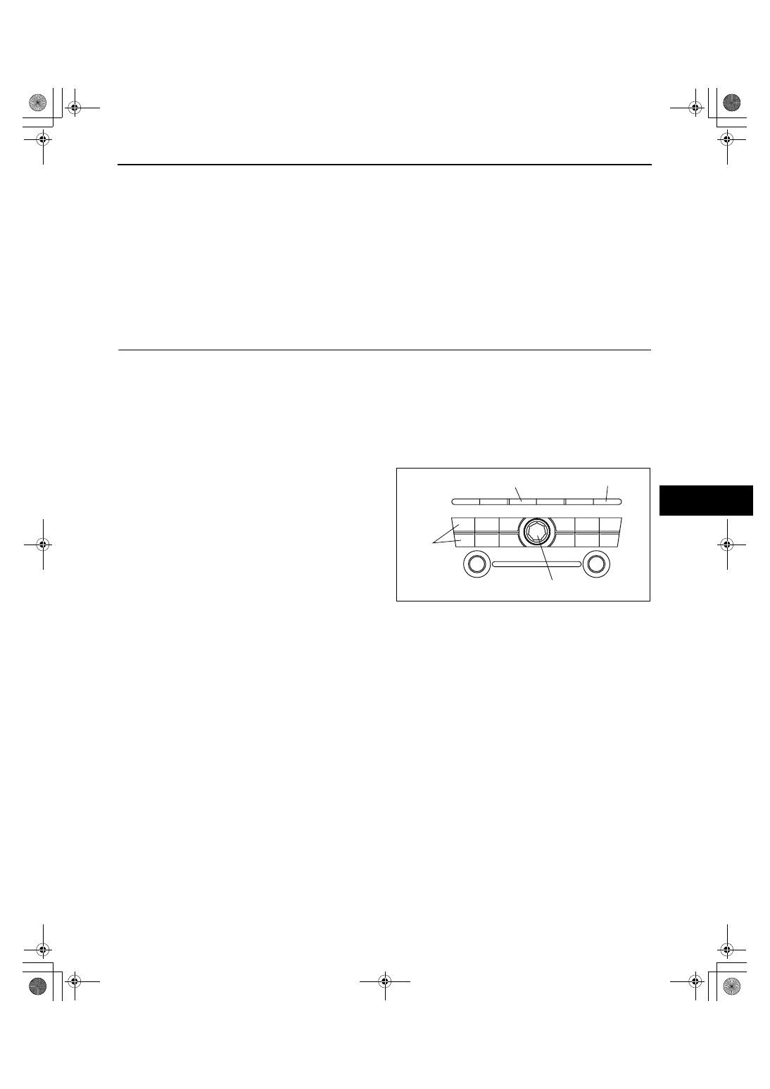
STARTING PROCEDURE FOR ON-BOARD DIAGNOSTIC TEST MODE[AUDIO]
id0902f6803700
Note
• All DTCs displayed in the on-board diagnostic test mode should be entered in the Audio Repair Order
Form.
1. Turn the ignition switch to the ACC or ON position.
2. Turn the POWER switch off.
3. While pressing the POWER button,
simultaneously press the FM/AM button and the
MEDIA button for 2 s or more.
Note
• If several DTCs are in the memory, they can
be displayed using the SEEK button (up or
down).
4. To stop the on-board diagnostic test mode, turn
the ignition switch off.
End Of Sie
SEEK
BUTTON
POWER BUTTON
FM/AM BUTTON
MEDIA BUTTON
acxuuw00001842
1871-1U-06B(09-02G).fm 1 ページ 2006年3月15日 水曜日 午前11時42分