Mazda CX 7. Manual - part 296


  Index      Mazda     Mazda CX 7 - service repair manual 2007 year


Search            


Content   ..  294  295  296  297   ..


Mazda CX 7. Manual - part 296


CONTROL SYSTEM 

07-40–9

07-40

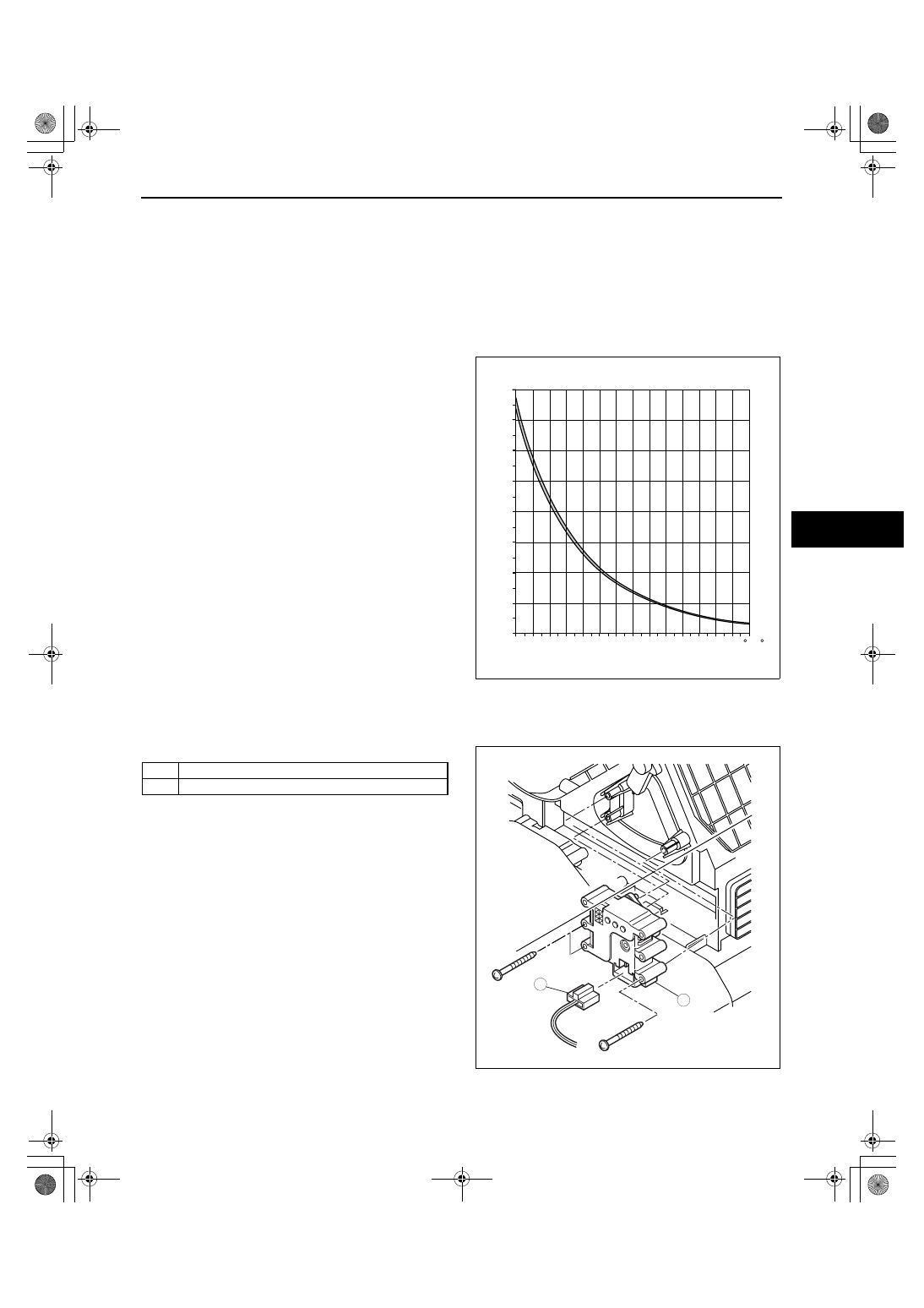
EVAPORATOR TEMPERATURE SENSOR INSPECTION

id074000801200

1. Set the fan speed MAX HI.
2. Set the temperature control at MAX COLD (Turn the left).
3. Turn the A/C switch off.
4. Set the RECIRCULATE mode.
5. Close all doors and windows.
6. Wait for 5 min.
7. Remove the glove compartment. (See 09-17-8 GLOVE COMPARTMENT REMOVAL/INSTALLATION.)
8. Disconnect the evaporator temperature sensor connector.
9. Measure the temperature at the blower inlet.

10. Measure the resistance between terminals of the 

evaporator temperature sensor.

• If the resistance is not as shown in the graph, 

replace the evaporator temperature sensor.

End Of Sie

WM: AIR INTAKE ACTUATOR

AIR INTAKE ACTUATOR REMOVAL/INSTALLATION

id074000801400

1. Disconnect the negative battery cable.
2. Remove the glove compartment. (See 09-17-8 GLOVE COMPARTMENT REMOVAL/INSTALLATION.)
3. Remove in the order indicated in the table.

4. Install in the reverse order of removal.

End Of Sie

16

14

12

10

8

6

4

2

0

-10
{14}

{32}

{50}

{68}

{86}

{104}

{122}

0

TEMPERATURE

KILOHM

RESIST

ANCE

10

20

30

40

50

{  F}

C

acxuuw00000978

1

Air intake actuator connector

2

Air intake actuator

1

2

acxuuw00001566

1871-1U-06B(07-40).fm  9 ページ  2006年3月16日 木曜日 午後4時1分

CONTROL SYSTEM 

07-40–10

AIR INTAKE ACTUATOR INSPECTION

id074000801500

1. Connect battery positive voltage to terminal D or F and ground to terminal F or D of the air intake actuator.
2. Verify that the air intake actuator operates as 

shown below.

• If there is any malfunction, replace the air 

intake actuator.

End Of Sie

WM: AIRFLOW MODE ACTUATOR

AIRFLOW MODE ACTUATOR REMOVAL/INSTALLATION

id074000801600

1. Disconnect the negative battery cable.
2. Remove the glove compartment. (See 09-17-8 GLOVE COMPARTMENT REMOVAL/INSTALLATION.)
3. Remove in the order indicated in the table.

4. Install in the reverse order of removal.

End Of Sie

Connection

Movement

B+

GND

D

F

RECIRCULATE 

→ FRESH

F

D

FRESH 

→ RECIRCULATE

30

°

90

°

FRESH

RECIRCULATE

D

F

*

*

*

*

acxuuw00001168

F

D

M

acxuuw00002306

1

Airflow mode actuator connector

2

Airflow mode actuator

1

2

acxuuw00001568

1871-1U-06B(07-40).fm  10 ページ  2006年3月16日 木曜日 午後4時1分

CONTROL SYSTEM 

07-40–11

07-40

AIRFLOW MODE ACTUATOR INSPECTION

id074000801700

Caution

• If the lever position exceeds the operation range shown in the figure, the circuit in the actuator 

could be damaged. Always perform an actuator operation inspection with the lever movement 
within the range shown in the figure.

1. Connect battery positive voltage to terminal D or F and ground to terminal F or D of the airflow mode actuator.
2. Verify that the airflow mode actuator operates as 

shown below.

• If there is any malfunction, replace the airflow 

mode actuator.

3. Verify that the resistance between the terminals of 

the airflow mode actuator is as shown in the 
graph.

• If there is any malfunction, replace the airflow 

mode actuator.

End Of Sie

WM: CLIMATE CONTROL UNIT

CLIMATE CONTROL UNIT DISASSEMBLY/ASSEMBLY

id074000802000

Full-auto Air Conditioner
Disassemble in the order indicated in the table.

Connection

Movement

B+

GND

D

F

DEFROSTER 

→ VENT

F

D

VENT 

→ DEFROSTER

VENT

DEFROSTER

F

D C B A

*

18.5

°

71.5

°

acxuuw00000725

M

F

D

B

C

A

VENT

DEFROSTER

acxuuw00000726

RESIST

ANCE

0.5

3.5

KILOHM

BETWEEN B
AND C
TERMINALS WIRE

BETWEEN C
AND A
TERMINALS WIRE

VENT

VENT

DEFROSTER

DEFROSTER

AIRFLOW MODE ACTUATOR POSITION

acxuuw00000727

1

Illumination bulb

2

Body

2

1

FULL-AUTO AIR CONDITIONER

REMOVAL

INSTALLATION

acxuuw00001839

1871-1U-06B(07-40).fm  11 ページ  2006年3月16日 木曜日 午後4時1分

CONTROL SYSTEM 

07-40–12

Manual Air Conditioner
Disassemble in the order indicated in the table.

Wire Disassembly Note

1. Disassemble the wire in the shown in the figure.

Wire Assembly Note

1. Assemble the wire to the position as shown in the 

figure.

End Of Sie

CLIMATE CONTROL UNIT WIRE ADJUSTMENT

id074000802100

Air Mix Wire

1. Set the temperature control dial to max cold.
2. Set the air mix link to max cold in the direction 

shown by the arrow and insert a screwdriver at 
the set hole.

3. Connect the air mix wire to the air mix link.
4. Clamp the air mix wire to the wire clamp.
5. Verify that the temperature control dial rotates at 

full stroke.

End Of Sie

SOKYU_WM: CLIMATE CONTROL UNIT

1

Knob

2

Air mix wire
(See 07-40-12 Wire Disassembly Note.)
(See 07-40-12 Wire Assembly Note.)

3

Airflow volume control dial

4

Illumination bulb

5

Body

1

4

4

3

2

5

MANUAL AIR CONDITIONER

acxuuw00000732

WIRE

CLIMATE CONTROL
UNIT

1

2

1

acxuuw00000733

AIR MIX WIRE

acxuuw00000734

MAX COLD

TEMPERATURE
CONTROL DIAL

MAX COLD

SET HOLE

AIR MIX LINK

acxuuw00001840

1871-1U-06B(07-40).fm  12 ページ  2006年3月16日 木曜日 午後4時1分


Content   ..  294  295  296  297   ..