Mazda CX 7. Manual - part 164


  Index      Mazda     Mazda CX 7 - service repair manual 2007 year


Search            


Content   ..  162  163  164  165   ..


Mazda CX 7. Manual - part 164


FRONT SUSPENSION 

02-13–11

02-13

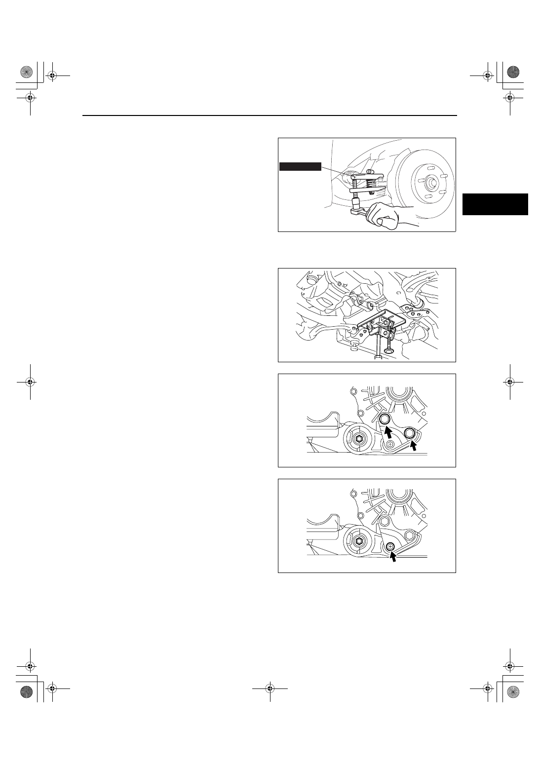
Tie-rod End Ball Joint Removal Note

1. Remove the tie-rod end ball joint locknut.
2. Disconnect the tie-rod end ball joint using the 

SST.

Steering Gear And Linkage, Front Stabilizer, Front Lower Arm And Front Crossmember Component 

Removal Note

1. Support the crossmember component with a jack.

2. Loosen the bolts of the No.1 engine mount 

(engine side).

3. Remove the No.1 engine mount bolt (engine 

side).

4. Lower the steering gear and linkage, front 

stabilizer, front lower arm and front crossmember 
component slightly.

49 T028  3A0

ampjjw00003208

acxuuw00001339

acxuuw00001689

acxuuw00001690

1871-1U-06B(02-13).fm  11 ページ  2006年3月15日 水曜日 午前11時0分

FRONT SUSPENSION 

02-13–12

5. Disconnect the return hose indicated in the figure.
6. Disconnect the pressure hose (power steering 

pump side) indicated in the figure.

Front Crossmember Mounting Rubber (front) Installation Note

1. Install the front crossmember mounting rubber 

(front) so that the smaller outer diameter is facing 
upward.

Front Crossmember Mounting Rubber (rear) Installation Note

1. Install the front crossmember mounting rubber 

(rear) so that the larger outer diameter is facing 
upward.

acxuuw00001691

FoMoCo

UPPER SIDE OF THE VEHICLE

acxuuw00001341

FoMoCo

UPPER SIDE OF THE VEHICLE

acxuuw00001342

1871-1U-06B(02-13).fm  12 ページ  2006年3月15日 水曜日 午前11時0分

FRONT SUSPENSION 

02-13–13

02-13

Steering Gear And Linkage, Front Stabilizer, Front Lower Arm And Front Crossmember Component 

Installation Note

1. Raise the steering gear and linkage, front 

stabilizer, front lower arm and front crossmember 
component to the appropriately level, and install 
the return hose and pressure hose.

Tightening torque

Return hose: 7.8— 10.8 N·m {80— 110 

kgf·cm, 69.1— 95.5 in·lbf}

Pressure hose (power steering pump side): 

29.4— 44.1 N·m {3.00— 4.49 kgf·m, 21.7— 
32.5 ft·lbf}

2. Temporarily install the No.1 engine mount bolt A 

indicated in the figure.

3. Tighten the No.1 engine mount bolts B indicated 

in the figure.

Tightening torque

93.1— 116.6 N·m {9.50— 11.8 kgf·m, 68.7— 

85.9 ft·lbf}

4. Teighten the No.1 engine mount bolt A at the 

specified torque.

Tightening torque

85.3— 116.6 N·m {8.70— 11.8 kgf·m, 63.0— 

85.9 ft·lbf}

5. Install the steering gear and linkage, front stabilizer, front lower arm and front crossmember component.
6. Tighten the No.1 engine mount bolt (crossmember side).

End Of Sie

WM: TRANSVERSE MEMBER

acxuuw00001691

A

B

acxuuw00001692

1871-1U-06B(02-13).fm  13 ページ  2006年3月15日 水曜日 午前11時0分

FRONT SUSPENSION 

02-13–14

TRANSVERSE MEMBER REMOVAL/INSTALLATION

id021300801100

1. Remove the transverse member.

2. Install the transverse member so that the arrow is 

pointing to the front of the vehicle.

3. Tighten the nut A, then tighten the bolts in the 

order of B, C to the specified torque.

Tightening torque

Nut A: 119.6— 154.8 N·m {12.20— 15.78 

kgf·m, 88.3— 114.1 ft·lbf}

Bolts B and C: 93.1— 131.3 N·m {9.50— 

13.38 kgf·m, 68.67— 96.84 ft·lbf}

End Of Sie

N·m {kgf·m, ft·lbf}

93.1—131.3 
{9.50—13.38, 
68.67—96.84}

93.1—131.3 
{9.50—13.38, 
68.67—96.84} 

119.6—154.8 
{12.20—15.78, 
88.3—114.1}

119.6—154.8 
{12.20—15.78, 
88.3—114.1}

TRANSVERSE 
MEMBER

acxuuw00001674

FRONT

acxuuw00001675

B

C

A

acxuuw00001676

1871-1U-06B(02-13).fm  14 ページ  2006年3月15日 水曜日 午前11時0分


Content   ..  162  163  164  165   ..