Mazda CX 7. Manual - part 90
SYMPTOM TROUBLESHOOTING [L3 WITH TC]
01-03–57
01-03
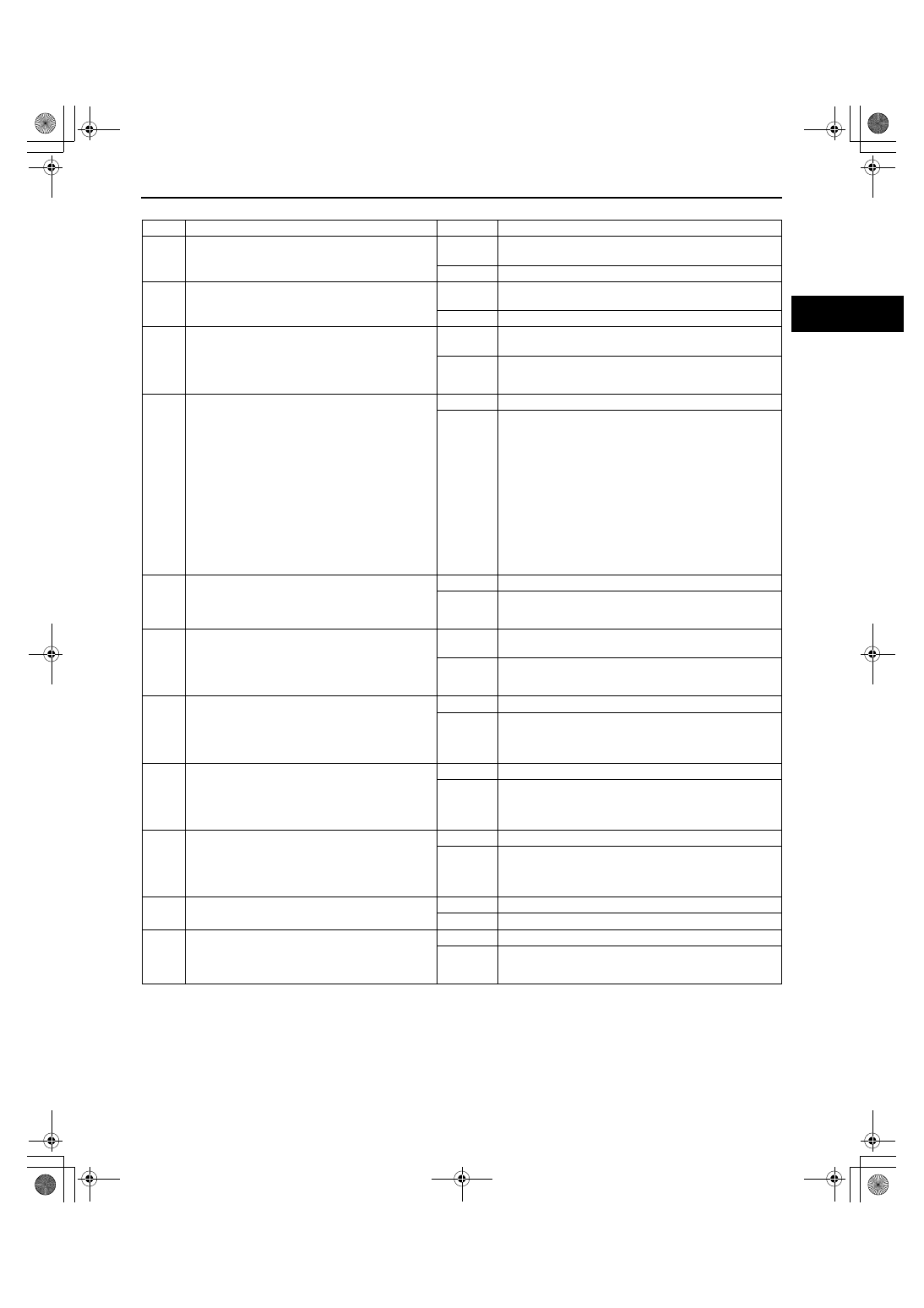
Diagnostic procedure
STEP
INSPECTION
RESULTS
ACTION
1
Is the engine overheating?
Yes
Go to symptom troubleshooting “NO.17 COOLING
SYSTEM CONCERNS - OVERHEATING.”
No
Go to the next step.
2
Is the engine runs cold?
Yes
Go to symptom troubleshooting “NO.18 COOLING
SYSTEM CONCERNS - RUNS COLD.”
No
Go to the next step.
3
Connect the M-MDS to the DLC.
Perform the self-test function using the M-MDS.
Turn the ignition switch to the ON position.
Retrieve any DTCs.
Is a DTC displayed?
Yes
DTC is displayed:
Go to appropriate DTC test.
No
No DTC is displayed:
Go to the next step.
4
Inspect for the following.
• Fuel quality (proper octane, contamination,
winter/summer blend)
• Charge air cooler condition (restriction or
damaged)
• Air cleaner element (clogging or restriction)
• Intake-air system leakage
• PCV valve installation
• Vacuum line leakage or blockage
• Fuel leakage at fuel system
• Charcoal canister damaged
• Exhaust system and/or three-way catalytic
converter restriction
Are all items normal?
Yes
Go to the next step.
No
Service if necessary.
Repeat Step 4.
5
Perform the EGR system operation inspection.
(See01-03-78 ENGINE CONTROL SYSTEM
OPERATION INSPECTION[L3 WITH TC].)
Does the EGR system operate properly?
Yes
Go to the next step.
No
Inspect or replace the malfunctioning parts, according
to the inspection results.
6
Perform the TP sweep inspection.
(See01-03-78 ENGINE CONTROL SYSTEM
OPERATION INSPECTION[L3 WITH TC].)
Does the electronic throttle control system work
properly?
Yes
Visually inspect the throttle body (damaged/
scratching.) If normal, go to the next step.
No
Inspect or replace the malfunctioning parts, according
to the inspection results.
7
Perform the Variable Swirl Control System
Operation Inspection.
(See01-03-78 ENGINE CONTROL SYSTEM
OPERATION INSPECTION[L3 WITH TC].)
Does the variable swirl system work properly?
Yes
Go to the next step.
No
Inspect or replace the malfunctioning parts, according
to the inspection results.
8
Perform the Wastegate Control System
Operation Inspection.
(See01-03-78 ENGINE CONTROL SYSTEM
OPERATION INSPECTION[L3 WITH TC].)
Does the variable swirl system work properly?
Yes
Go to the next step.
No
Inspect or replace the malfunctioning parts, according
to the inspection results.
9
Perform the Evaporative Emission (EVAP)
System Leak Inspection.
(See01-03-78 ENGINE CONTROL SYSTEM
OPERATION INSPECTION[L3 WITH TC].)
Does the variable swirl system work properly?
Yes
Go to the next step.
No
Inspect or replace the malfunctioning parts, according
to the inspection results.
10
Remove and shake the PCV valve.
Does the PCV valve rattle?
Yes
Go to the next step.
No
Replace the PCV valve.
11
Perform the spark test.
(See01-03-78 ENGINE CONTROL SYSTEM
OPERATION INSPECTION[L3 WITH TC].)
Is a strong blue spark visible at each cylinder?
Yes
Go to the next step.
No
Inspect or replace the malfunctioning parts, according
to the inspection results.
1871-1U-06B(01-03).fm 57 ページ 2006年3月15日 水曜日 午前10時36分