Mazda 6. Manual - part 379


  Index      Mazda     Mazda 6 - service repair manual 2002 year


Search            


Content   ..  377  378  379  380   ..


Mazda 6. Manual - part 379


BASIC SYSTEM 

U–21

U

UHEATER AND AIR CONDITIONER SYSTEMS

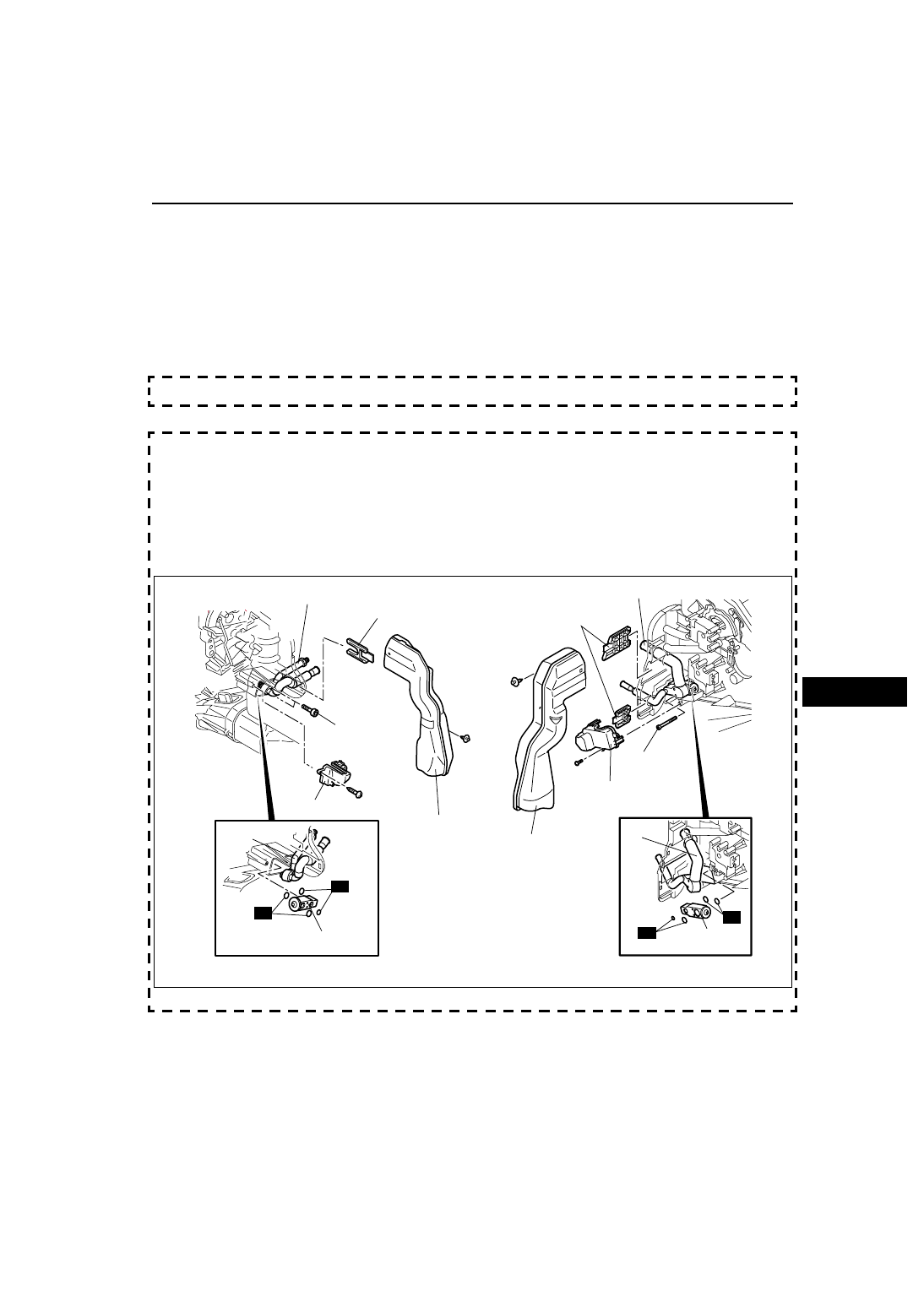
EXPANSION VALVE REMOVAL/INSTALLATION

A6E851661130W03

1. Disconnect the negative battery cable.
2. Discharge the refrigerant from the system. (See 

U–9 RECOVERY

.) (See 

U–9 CHARGING

.) 

Caution

• If moisture or foreign material enters the refrigeration cycle, cooling ability will be lowered and 

abnormal noise will occur. Always immediately plug open fittings after removing any refrigeration 
cycle parts to keep moisture or foreign material out of the cycle.

3. Disconnect the cooler hose (Lo) (L.H.D) or cooler pipe No.4 (R.H.D.) and cooler pipe No.3. (See 

U–25 

REFRIGERANT LINES REMOVAL/INSTALLATION

.)

4. Remove the passenger-side air bag module. (See 

T–121 PASSENGER-SIDE AIR BAG MODULE REMOVAL/

INSTALLATION

.)

5. Remove the duct (1).
6. Remove the air mix actuator. (Full-auto air conditioner)
7. Remove the adhesive polyurethane (1). (See 

U–20–2 Adhesive polyurethane (1) Assembly Note

.)

8. Remove the screws and cover. (Type A and type B)
9. Remove the one seal plate (L.H.D. type A and type B, R.H.D. type C) or two seal plates (R.H.D. type A and 

type B).

10. Remove the bolts (type A and type B) or one bolt (type C) and shift the outlet pipe. Do not allow compressor oil 

to spill.

11. Remove the two bolts. (Type C)
12. Remove the expansion valve. Do not allow compressor oil to spill.
13. Remove the screws and plate. (Type C)
14. Remove the adhesive polyurethane (2). (Type C) (See 

U–20–1 Adhesive polyurethane (2) Assembly Note

.)

End Of Sie

BASIC SYSTEM

L.H.D.
TYPE A

R.H.D.
TYPE A

 N·m {kgf·cm,  in·lbf}

R

3.5—5.5 

  {36—56, 31—48}

OUTLET PIPE

SEAL PLATE

DUCT (1)

COVER

SHIFT

EXPANSION VALVE

R

3.5—5.5 

  {36—56, 31—48}

OUTLET PIPE

SEAL PLATE

DUCT (1)

COVER

SHIFT

EXPANSION
VALVE

R

R

B6E8516W013

BASIC SYSTEM 

U–21–1

U–21HEATER AND AIR CONDITIONER SYSTEMS

End Of Sie

BASIC SYSTEM

L.H.D.
TYPE B

R.H.D.
TYPE B

 N·m {kgf·cm,  in·lbf}

R

3.5—5.5 

  {36—56, 31—48}

OUTLET PIPE

SEAL PLATE

DUCT (1)

COVER

SHIFT

EXPANSION VALVE

R

3.5—5.5 

  {36—56, 31—48}

OUTLET PIPE

SEAL PLATE

DUCT (1)

COVER

SHIFT

EXPANSION
VALVE

R

R

ADHESIVE
POLYURETHANE (1)

ADHESIVE
POLYURETHANE (1)

B6E8516W014

L.H.D.
TYPE C

R.H.D.
TYPE C

 N·m {kgf·cm,  in·lbf}

R

3.5—5.5 

  {36—56, 31—48}

OUTLET PIPE

DUCT (1)

PLATE

SHIFT

EXPANSION VALVE

R

3.5—5.5 

  {36—56, 31—48}

OUTLET PIPE

SEAL
PLATE

DUCT (1)

PLATE

SHIFT

EXPANSION
VALVE

R

R

ADHESIVE
POLYURETHANE (1)

ADHESIVE
POLYURETHANE (1)

ADHESIVE
POLYURETHANE (2)

ADHESIVE
POLYURETHANE (2)

3.5—5.5 

  {36—56, 31—48}

3.5—5.5 

  {36—56, 31—48}

R

R

R

R

B6E8516W015

U–22

BASIC SYSTEM 

UHEATER AND AIR CONDITIONER SYSTEMS

15. Install in the reverse order of removal.
16. Perform the refrigerant system performance test. (See 

U–13 REFRIGERANT SYSTEM PERFORMANCE 

TEST

.)

End Of Sie

EVAPORATOR INSPECTION

A6E851661810W01

1. Remove the A/C unit. (See 

U–15 A/C UNIT REMOVAL/INSTALLATION

.)

2. Remove the evaporator from the A/C unit.
3. Inspect for cracks, damage, and oil leakage.

• If any problems are found, replace the evaporator.

4. Inspect for bent fins.

• If any are bent, use a flathead screwdriver to straighten them.

End Of Sie

BASIC SYSTEM

BASIC SYSTEM 

U–23

U

HEATER CORE INSPECTION

A6E851661910W01

1. Remove the A/C unit. (See 

U–15 A/C UNIT REMOVAL/INSTALLATION

.)

2. Remove the heater core from the A/C unit.
3. Inspect for cracks, damage, and coolant leakage.

• If any problems are found, replace the heater core.

4. Inspect for bent fins.

• If any are bent, use a flathead screwdriver to straighten them.

5. Verify that the heater core inlet and outlet pipe are not distorted or damaged.

• Repair with pliers if necessary.

End Of Sie

REAR HEAT DUCT REMOVAL/INSTALLATION

A6E851661273W01

1. Turn over the front floor covering. (See 

S–99 FRONT FLOOR COVERING REMOVAL/INSTALLATION

.)

2. Remove in the order indicated in the table.

.

3. Install in the reverse order of removal.

End Of Sie

A/C COMPRESSOR REMOVAL/INSTALLATION

A6E851661450W01

1. Disconnect the negative battery cable.
2. Discharge the refrigerant from the system. (See 

U–9 RECOVERY

.) (See 

U–9 CHARGING

.)

3. Remove the right side splash shield and mudguard (L.H.D. only).
4. Loosen the drive belt and remove it.

Caution

• If moisture or foreign material enters the refrigeration cycle, cooling ability will be lowered and 

abnormal noise will occur. Always immediately plug open fittings after removing any refrigeration 
cycle parts to keep moisture or foreign material out of the cycle.

5. Remove in the order indicated in the table. Do not 

allow compressor oil to spill.

.

6. Install in the reverse order of removal.
7. Adjust the drive belt.
8. Perform the refrigerant system performance test. 

(See 

U–13 REFRIGERANT SYSTEM 

PERFORMANCE TEST

.)

1

Rear heat duct (Right)

2

Rear heat duct (Left)

A6E8516W011

1

Cooler hose (HI)
(See 

U–29 Refrigerant Lines Installation Note

)

2

Cooler pipe No.4 (L.H.D.) or cooler hose (LO) 
(R.H.D.)
(See 

U–29 Refrigerant Lines Installation Note

)

3

Magnetic clutch connector

4

A/C  compressor
(See 

U–24 A/C Compressor Installation Note

)

A6E8516W012


Content   ..  377  378  379  380   ..