Mazda 6. Manual - part 376


  Index      Mazda     Mazda 6 - service repair manual 2002 year


Search            


Content   ..  374  375  376  377   ..


Mazda 6. Manual - part 376


REFRIGERANT SYSTEM SERVICE PROCEDURES 

U–13

U

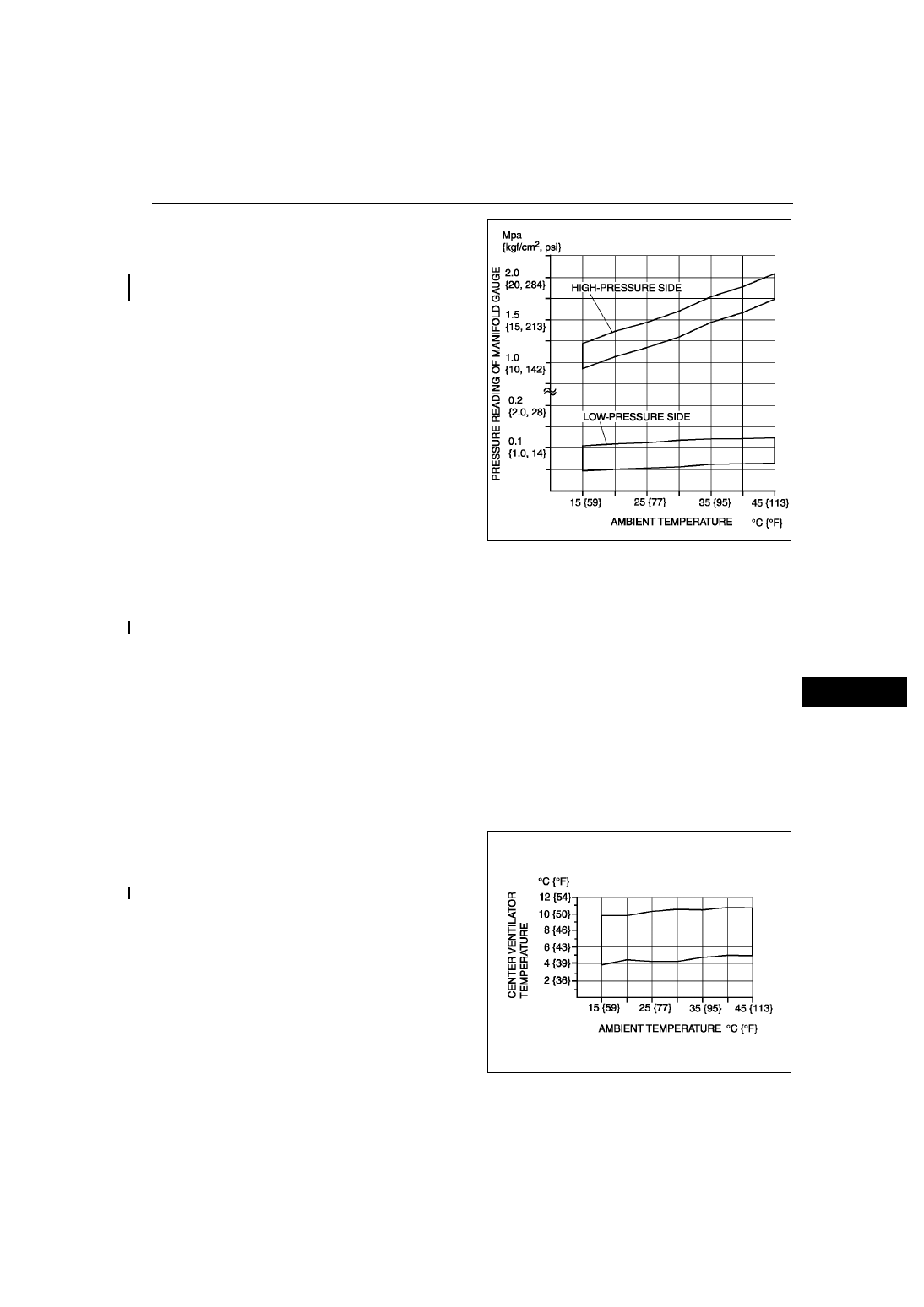
10. Verify that the intersection of the pressure reading 

of the SST (49 C061 001) and ambient 
temperature is in the shaded zone.

• If not as specified, troubleshoot the refrigerant 

system. (See 

U–64 TROUBLESHOOTING 

INDEX

.)

End Of Sie

REFRIGERANT SYSTEM PERFORMANCE TEST

A6E851401039W02

1. Perform refrigerant pressure check. (See 

U–12 REFRIGERANT PRESSURE CHECK

.)

• If they are correct, go to next step.

• If not as specified, troubleshoot the refrigerant system. (See 

U–64 TROUBLESHOOTING INDEX

.)

2. Place a dry-bulb thermometer in the driver-side center ventilator outlet.
3. Warm up the engine and run it at a constant 1,500 rpm.
4. Set the fan speed to MAX HI.
5. Turn the A/C switch on.
6. Set the RECIRCULATE mode.
7. Set the temperature control to MAX COLD.
8. Set the VENT mode.
9. Close all the doors and all the windows.

10. Wait until the air conditioner output temperature stabilizes.

Stabilized condition

• The A/C compressor is repeatedly turned on and off based on the A/C compressor control of center panel 

(manual air conditioner) or climate control unit (full-auto air condtioner).

11. Record driver-side center ventilator outlet temperature.
12. Determine and record ambient temperature.
13. Verify that the temperature reading is in the 

shaded zone.

• If the performance is not within the shaded 

zone, troubleshoot the refrigerant system. 
(See 

U–64 TROUBLESHOOTING INDEX

.)

End Of Sie

A6E8514W001

A6E8514W002

U–14

BASIC SYSTEM 

BLOWER UNIT REMOVAL/INSTALLATION

A6E851661140W01

1. Disconnect the negative battery cable.
2. Remove the dashboard. (See 

S–82 DASHBOARD REMOVAL/INSTALLATION

.)

3. Remove the A/C unit. (See 

U–15 A/C UNIT REMOVAL/INSTALLATION

.)

4. Remove the blower unit.
5. Install in the reverse order of removal.

End Of Sie

BLOWER UNIT DISASSEMBLY/ASSEMBLY

A6E851661140W02

1. Disassemble in the order indicated in the table.

Caution

• Apply only the specified grease to the link. Otherwise abnormal noise or improper operation may 

result.

.

2. Assemble in the reverse order of disassembly.

End Of Sie

BASIC SYSTEM

A6E8516W001

1

Air filter cover

2

Air filter

3

Blower  motor

4

Air intake actuator

5

Air intake crank

6

Air intake door

7

Polyurethane protector

8

Blower case (1)

9

Blower case (2)

A6E8516W002

BASIC SYSTEM 

U–15

U

AIR FILTER REMOVAL/INSTALLATION

A6E851661140W03

1. Remove the glove compartment.
2. Remove in the order indicated in the table.

3. Install in the reverse order of removal.

End Of Sie

AIR FILTER INSPECTION

A6E851661140W04

1. Remove the air filter.
2. Inspect the air filter.

• If the air filter is damaged, excessively dirty, or foul smelling, replace the air filter.

Note

• The air filter cannot be reused by cleaning it with water or compressed air.

• Replace the air filter at the following interval, depending on operating conditions.

End Of Sie

A/C UNIT REMOVAL/INSTALLATION

A6E851661130W01

1. Disconnect the negative battery cable.
2. Discharge the refrigerant from the system. (See 

U–9 RECOVERY

.) (See 

U–9 CHARGING

.) 

3. Drain the engine coolant. (See 

E–4 ENGINE COOLANT REPLACEMENT

.)

4. Remove the dashboard. (See 

S–82 DASHBOARD REMOVAL/INSTALLATION

.)

5. Remove the theft-deterrent control module. (See 

T–86 THEFT-DETERRENT CONTROL MODULE REMOVAL/

INSTALLATION

.)

Caution

• If moisture or foreign material enters the refrigeration cycle, cooling ability will be lowered and 

abnormal noise will occur. Always immediately plug open fittings after removing any refrigeration 
cycle parts to keep moisture or foreign material out of the cycle.

1

Air filter cover

2

Air filter

A6E8516W018

Destinations

Type

Interval (year or 

km {miles})

Europe (L.H.D. 
U.K.) specs.

Aldehyde, pollen, 
and a dust removal 

1 or 20,000 

{12,500}

Pollen, and a dust 
removal

2 or 40,000 

{25,000}

GCC specs.

1 or 20,000 

{12,500}

U–16

BASIC SYSTEM 

6. Remove in the order indicated in the table. Do not 

allow compressor oil to spill.

A6E8516W003

A6E8516W025

A6E8516W004

A6E8516W026


Content   ..  374  375  376  377   ..