Mazda 6. Manual - part 370
ON-BOARD DIAGNOSTIC [AIR BAG SYSTEM]
T–227
T
End Of Sie
DTC B2867
A6E817401046W25
3
VERIFY WHETHER MALFUNCTION IS IN
PASSENGER-SIDE CURTAIN AIR BAG
MODULE OR RELATED WIRING HARNESS
• Connect leads of SST (Fuel and
thermometer checker) or apply 2 ohm
resistor to passenger-side curtain air bag
module connector terminal A and B.
• Set resistance of SST (Fuel and
thermometer checker) to 2 ohm.
• Connect negative battery cable.
• Turn ignition switch to ON position.
• Check following PID/DATA monitor, using
SST (WDS or equivalent).
(See
— DO_P_CURT
• Is related wiring harness normal?
Yes
Replace passenger-side curtain air bag module.
(See
T–122 CURTAIN AIR BAG MODULE REMOVAL/
)
No
Replace wiring harness, then go to next step.
4
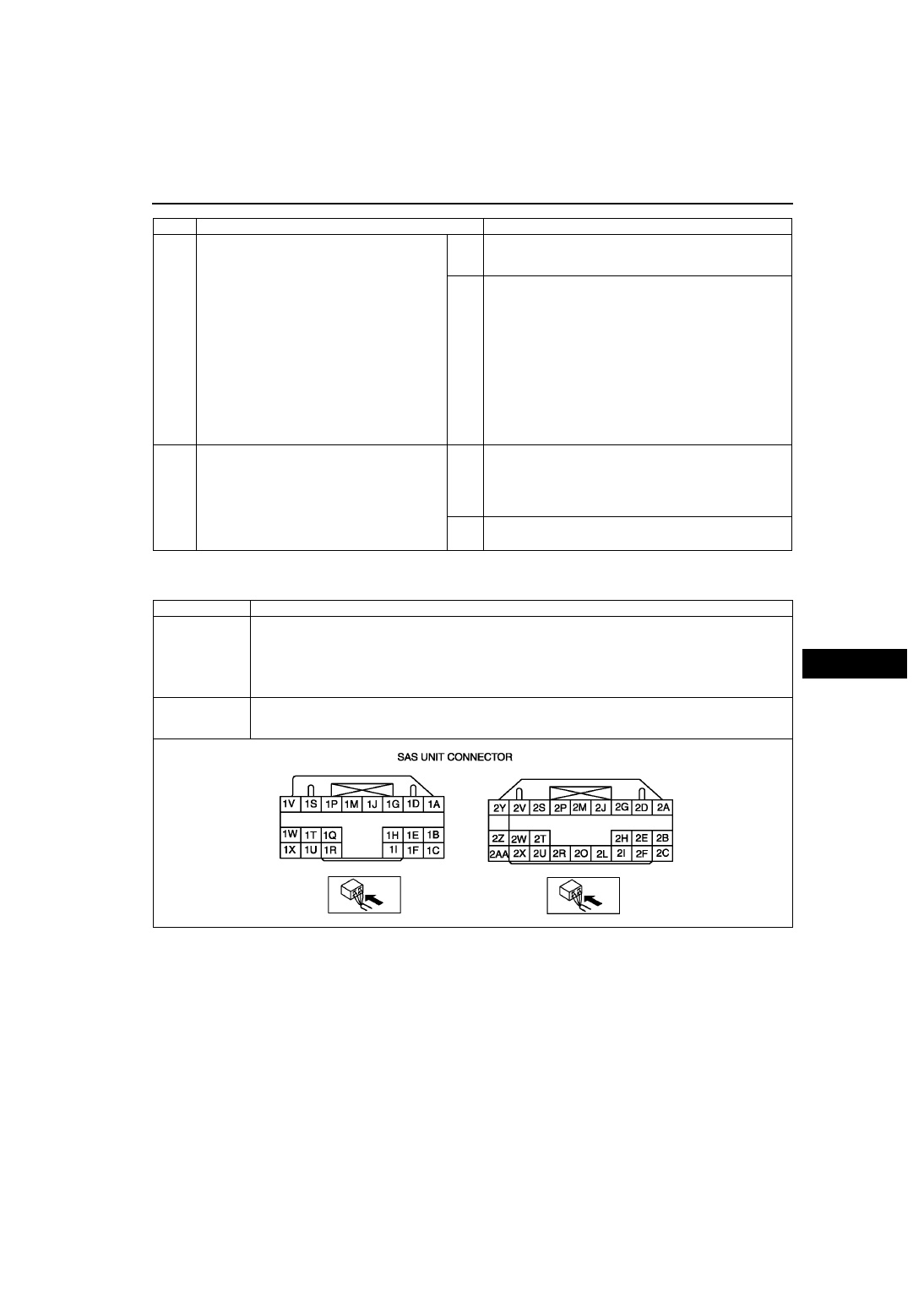
INSPECT SAS UNIT
• Turn ignition switch to LOCK position.
• Disconnect negative battery cable and wait
for more than 1 minute.
• Connect passenger-side curtain air bag
module connector.
• Are DTCs B2777, B2778, B2779 and/or
B2780 indicated?
Yes
Present malfunction diagnosis:
• Replace SAS unit.
T–124 SAS UNIT REMOVAL/INSTALLATION
)
Past malfunction diagnosis:
• Troubleshooting completed.
No
Troubleshooting completed.
STEP
INSPECTION
ACTION
DTC B2867
SAS unit connector poor connection
DETECTION
CONDITION
Warning
• Detection conditions are for understanding DTC outline before performing inspection.
Performing inspection with only detection conditions may cause injury due to operating error
or damage the system. When performing inspection, always follow inspection procedure.
• There is no continuity between poor connection detector bar terminals of SAS unit.
POSSIBLE
CAUSE
• Poor connection of any SAS unit connectors
• Malfunction of any SAS unit connectors
• SAS unit malfunction