Mazda 6. Manual - part 355
ON-BOARD DIAGNOSTIC [AUDIO]
T–167
T
Diagnostic procedure
End Of Sie
DTC 09:ER20
A6E817566900W06
Diagnostic procedure
INSPECTION
ACTION
INSPECT BASE UNIT
• Clear DTC.
• Turn on radio and operate it for 3 seconds or more.
• Start on-board diagnostic test mode.
• Is DTC 09:Er22 displayed?
Yes
Replace base unit.
No
Troubleshooting completed.
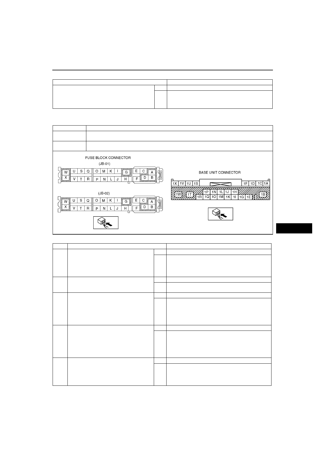
DTC 09:Er20
Power supply circuit of base unit
DETECTION
CONDITION
• Voltage detected at base unit terminals 1B and 1R is less than 8.5 V, or more than 16 V (must not be
16V).
POSSIBLE
CAUSE
• Weak battery
• Malfunction in wiring harness between battery and base unit
STEP
INSPECTION
ACTION
1
INSPECT FUSE
• Remove MIRROR 5 A fuse and ROOM 15 A
fuse.
• Inspect MIRROR 5 A fuse and ROOM 15 A
fuse.
• Are fuses okay?
Yes
Go to next step.
No
Replace fuse.
2
INSPECT BATTERY
• Measure battery voltage.
• Is voltage 8.5 V —16 V?
Yes
Go to next step.
No
Battery is weak.
• Inspect charge/discharge system.
3
INSPECT WIRING HARNESS BETWEEN
BATTERY AND FUSE BLOCK
• Turn ignition switch to ACC position.
• Measure voltage at fuse block connector
(JB-01) terminals B and fuse block connector
(JB-02) terminals D.
• voltage 8.5 V —16 V?
Yes
Go to next step.
No
Repair wiring harness between battery and fuse block.
4
INSPECT WIRING HARNESS BETWEEN
FUSE BLOCK AND BASE UNIT
• Install MIRROR 5 A fuse and ROOM 15 A
fuse.
• Measure voltage at base unit connector
terminals 1B and 1R.
• Is voltage 8.5 V —16 V?
Yes
Go to next step.
No
Repair wiring harness between fuse block and base unit.
5
INSPECT BASE UNIT
• Clear DTC.
• Turn ignition switch to ACC or ON position
and hold for 30 seconds or more.
• Start on-board diagnostic test mode.
• Is DTC 09:Er20 displayed?
Yes
Replace base unit.
No
Troubleshooting completed.