Mazda 6. Manual - part 268


  Index      Mazda     Mazda 6 - service repair manual 2002 year


Search            


Content   ..  266  267  268  269   ..


Mazda 6. Manual - part 268


WHEEL ALIGNMENT, WHEEL AND TIRE 

R–7

R

2. Adjust the toe-in turning the adjusting link.

Specification

Total Toe-in: 2

±4 mm {0.08±0.16 in} 

Note

• Toe change amount: 0°43′ / one rotation

3. Tighten the locknut.

Tightening torque

68.6—98.1 N·m 

{7.0—10.0 kgf·m, 50.6—72.3 ft·lbf}

End Of Sie

WHEEL BALANCE ADJUSTMENT (16 INCH AND 17 INCH  ALUMINUM ALLOY WHEEL)

A6E741701014W01

Caution

• Adjust the outer wheel balance first, then the inner wheel balance.

• Be careful not to scratch the wheels.

Adhesive-type Balance Weight (Outer)

1. Remove the old balance weight from the wheel.
2. Remove the double-sided adhesive tape remaining on the wheel, then clean and degrease the bonding area.
3. Set the wheel on a wheel balancer, measure the amount of unbalance and the position with the mode set for 

knock-type balance weight.

4. Multiply the amount of unbalance by 1.6 to get the balance weight value.
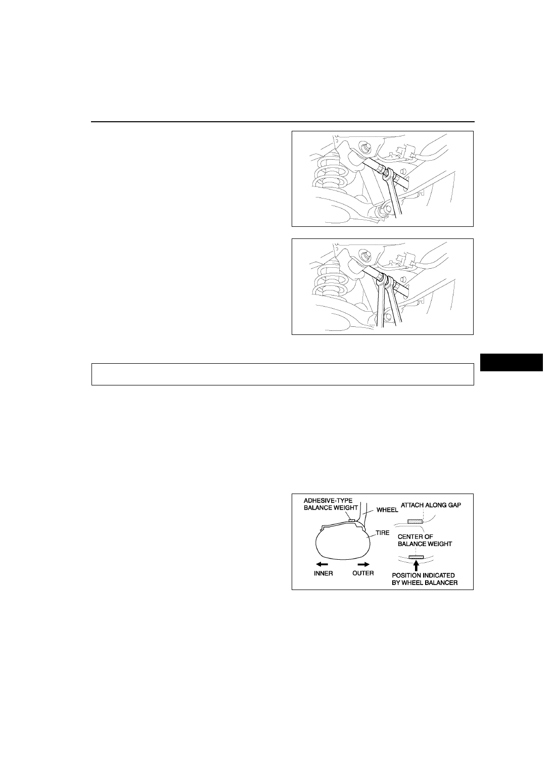
5. Select a balance weight closest to the weight 

value and attach the balance weight on the 
position (outer) indicated by the wheel balancer.

Example calculation of balance weight value

Indicated amount of unbalance: 23 g 

{0.81 oz}
23 g {0.81 oz}

×1.6 = 36.8 g {1.30 oz}

Selected balance weight value: 35 g 

{1.24 oz}

Note

• When selecting a balance weight, select one 

closest to the calculated value. 
 Example: 32.4 g {1.14 oz}= 30 g {1.06 oz}, 32.5 g {1.15 oz}= 35 g {1.24 oz}

Caution

• Use a genuine balance weight or equivalent (steel).

• When attaching the weight balance, press the balance weight with a force of 25 N {2.5 kgf, 5.5 lbf} 

per 5 g for 2 seconds or more.

A6E7412W005

A6E7412W004

WHEEL AND TIRE

Z5U0212W101

R–8

WHEEL AND TIRE 

6. If attaching 2 balance weights, position them so 

that each is on either side of the position indicated 
by the wheel balancer.

Caution

• Do not attach weight balances in a row.

• Do not overlap the balance weights.

• Total weight must not exceed 160g 

{5.65 oz}.

Knock-type Balance Weight (Inner)

1. Measure the amount of unbalance with a wheel balancer.
2. Attach a balance weight corresponding to the 

measured weight value on the position (inner) 
indicated by the wheel balancer.

Caution

• Do not attach 3 or more balance weights.

• One balance weight must not exceed 60g 

{2.12 oz}, and a total of 2 balance weights 
must not exceed 100g {3.53 oz}.

Remaining Amount of Unbalance Confirmation

1. After installing the outer and inner balance weights, operate the wheel balancer again.
2. Confirm that the remaining unbalance does not exceed followings on either side.

• If the remaining unbalance exceeds 10 g {0.35 oz} (16 inch wheel) or 9g {0.32 oz} (17 inch wheel), perform 

wheel balance adjustment again.

Allowable remaining unbalance value (g)

End Of Sie

Z5U0212W102

Z5U0212W103

Outer

Inner

16 inch wheel

10 g {0.35 oz}

8 g {0.28 oz}

17 inch wheel

9 g {0.32 oz}

7 g {0.25 oz}

Dynamic unbalance (at rim)

Static 

unbalance 

(at rim)

Outer

Inner

16 inch 
wheel

10 g {0.35 oz} 

max.

8 g {0.28 oz} 

max.

13 g {0.46 oz} 

max.

17 inch 
wheel

9 g {0.32 oz} 

max.

7 g {0.25 oz} 

max.

11 g {0.39 oz} 

max.

FRONT SUSPENSION 

R–9

R

FRONT SHOCK ABSORBER AND SPRING REMOVAL/INSTALLATION

A6E741404910W01

Caution

• Performing the following procedures without first removing the ABS wheel-speed sensor may 

possibly cause an open circuit in the harness if it is pulled by mistake. Before performing the 
following procedures, remove the ABS wheel-sensor (axle side) and fix it to an appropriate place 
where the sensor will not be pulled by mistake while servicing the vehicle.

1. Remove in the order indicated in the table.
2. Install in the reverse order of removal.

.

FRONT SUSPENSION

A6E7414W017

1

Bolt (ABS wheel-speed sensor)

2

Bolt (brake hose bracket)

3

Nut (front stabilizer control link)

4

Bolt (front shock absorber lower side)
(See 

R–10 Bolt (Front Shock Absorber Lower Side) 

Removal Note

)

5

Dynamic damper

6

Damper fork
(See 

R–12 Damper Fork Installation Note

)

7

Nut (front shock absorber upper side)

8

Front shock absorber and coil spring
(See 

R–11 Front Shock Absorber and Coil Spring 

Installation Note

)

9

Piston rod nut
(See 

R–10 Piston Rod Nut Removal Note

)

10

Mounting rubber

11

Bound stopper

12

Dust boot

13

Coil spring
(See 

R–10 Coil Spring Installation Note

)

14

Front shock absorber

R–10

FRONT SUSPENSION 

Bolt (Front Shock Absorber Lower Side) Removal Note

1. Support the knuckle with a jack to prevent from falling.

Piston Rod Nut Removal Note

Warning

• Removing the piston rod nut is dangerous. The shock absorber and spring could fly off under 

tremendous pressure and cause serious injury or death. Secure the shock absorber in the SSTs 
before removing the piston rod nut.

1. Protect the coil spring using a piece of cloth, then set the SSTs.
2. Compress the coil spring using the SSTs, and 

remove the piston rod nut.

Coil Spring Installation Note

1. Temporarily install the coil spring, dust boot and mounting rubber on the shock absorber so that the lower end 

of the coil spring is seated on the step of the lower spring seat.

2. Mark the coil spring, dust boot and mounting 

rubber for proper installation as shown in the 
figure.

3. Align the marks of the coil spring and dust boot. 

Protect the coil spring and dust boot using a piece 
of cloth, then set the SSTs.

A6E7414W008

A6E7414W039


Content   ..  266  267  268  269   ..