Mazda 6. Manual - part 253
P–68
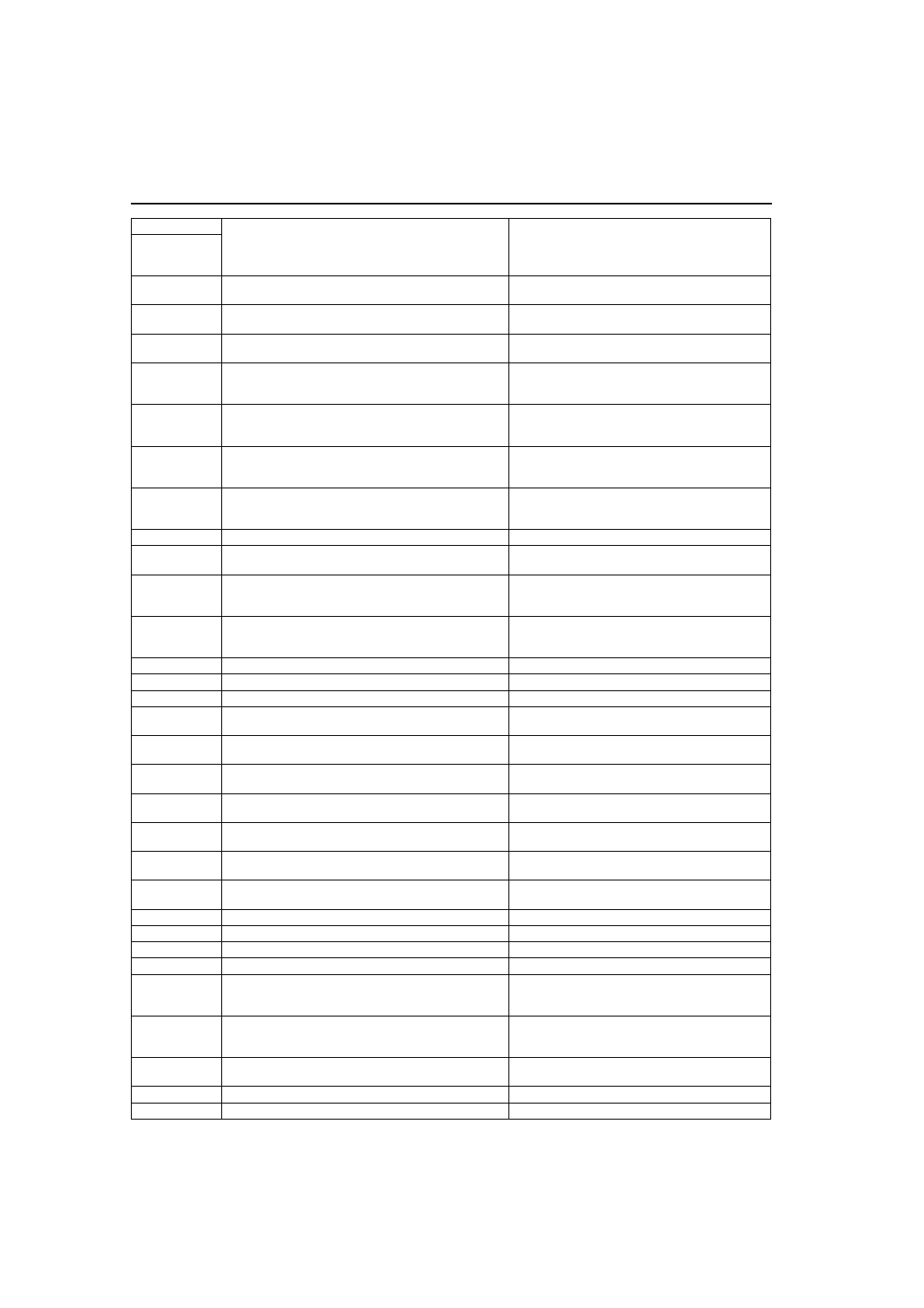
ON-BOARD DIAGNOSTIC (DYNAMIC STABILITY CONTROL)
C1234
Right front wheel-speed sensor/sensor rotor
(See
P–83 DTC C1148, C1158, C1168, C1178,
C1235
Right rear wheel-speed sensor/sensor rotor
(See
P–83 DTC C1148, C1158, C1168, C1178,
C1236
Left rear wheel-speed sensor/sensor rotor
(See
P–83 DTC C1148, C1158, C1168, C1178,
C1242
Left rear pressure reduction solenoid valve
(See
P–87 DTC C1194, C1198, C1210, C1214,
C1242, C1246, C1250, C1254, C1400, C1410,
C1957, C1958
)
C1246
Right rear pressure reduction solenoid valve
(See
P–87 DTC C1194, C1198, C1210, C1214,
C1242, C1246, C1250, C1254, C1400, C1410,
C1957, C1958
)
C1250
Left rear pressure retention solenoid valve
(See
P–87 DTC C1194, C1198, C1210, C1214,
C1242, C1246, C1250, C1254, C1400, C1410,
C1957, C1958
)
C1254
Right rear ABS pressure retention solenoid valve
(See
P–87 DTC C1194, C1198, C1210, C1214,
C1242, C1246, C1250, C1254, C1400, C1410,
C1957, C1958
)
C1266
Fail-safe relay
(See
)
C1280
Combine sensor
(See
P–88 DTC C1280, C1730, C1951, C1952,
C1400
Right front traction switch solenoid valve
(See
P–87 DTC C1194, C1198, C1210, C1214,
C1242, C1246, C1250, C1254, C1400, C1410,
C1957, C1958
)
C1410
Left front traction switch solenoid valve
(See
P–87 DTC C1194, C1198, C1210, C1214,
C1242, C1246, C1250, C1254, C1400, C1410,
C1957, C1958
)
C1414
DSC HU/CM
(See
C1507
DSC control
(See
)
C1508
DSC control
(See
)
C1510
Right front solenoid valve, motor or wheel-speed
sensor/sensor rotor
(See
P–92 DTC C1510, C1511, C1512, C1513
C1511
Left front solenoid valve, motor or wheel-speed sensor/
sensor rotor
(See
P–92 DTC C1510, C1511, C1512, C1513
C1512
Right rear solenoid valve, motor or wheel-speed
sensor/sensor rotor
(See
P–92 DTC C1510, C1511, C1512, C1513
C1513
Left rear solenoid valve, motor or wheel-speed sensor/
sensor rotor
(See
P–92 DTC C1510, C1511, C1512, C1513
C1730
Combine sensor
(See
P–88 DTC C1280, C1730, C1951, C1952,
C1951
Combine sensor
(See
P–88 DTC C1280, C1730, C1951, C1952,
C1952
Combine sensor
(See
P–88 DTC C1280, C1730, C1951, C1952,
C1953
Brake fluid pressure sensor
(See
)
C1954
Brake fluid pressure sensor
(See
)
C1955
Steering angle sensor
(See
)
C1956
Steering angle sensor
(See
)
C1957
Right front DSC switch solenoid valve
(See
P–87 DTC C1194, C1198, C1210, C1214,
C1242, C1246, C1250, C1254, C1400, C1410,
C1957, C1958
)
C1958
Left front DSC switch solenoid valve
(See
P–87 DTC C1194, C1198, C1210, C1214,
C1242, C1246, C1250, C1254, C1400, C1410,
C1957, C1958
)
C1959
Combine sensor
(See
P–88 DTC C1280, C1730, C1951, C1952,
U1900
Can communication
(See
)
U2021
Invalid/fault data received
(See
DTC
Diagnosis system component
Page
WDS or
equiva-
lent