Mazda 6. Manual - part 247
 

  Index      Mazda     Mazda 6 - service repair manual 2002 year


Search            


Content   ..  245  246  247  248   ..


Mazda 6. Manual - part 247


P–44

DYNAMIC STABILITY CONTROL 

2)

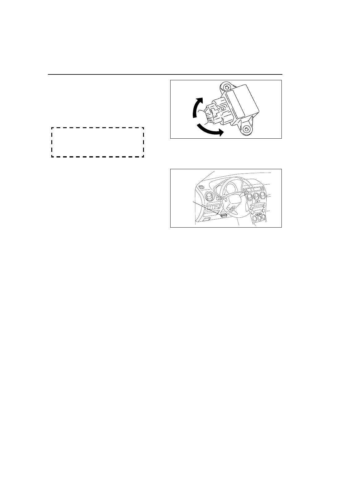
Measure voltage at output terminal D and 
ground terminal E when the yaw rate 
sensor is rotated left and right.

Caution

• Be careful when turning the yaw rate 

sensor rotation position while it is in a 
reversed state because the rotation 
direction and voltage will be reversed.

Voltage

Right rotation:

 fluctuation between 2.5—4.62 V

Left rotation: 

fluctuation between 2.5—0.33 V

End Of Sie

COMBINE SENSOR INITIALIZATION PROCEDURE

A6E692067650W07

1. Set the SST (WDS or equivalent) to the DLC-2
2. Access the active command mode and select the 

YAWRATE, then follow the indication on the 
monitor.

3. Select the LATACCEL and follow the indication on 

the monitor.

End Of Sie

STEERING ANGLE SENSOR REMOVAL/INSTALLATION

A6E692067650W08

1. (See 

T–38 COMBINATION SWITCH DISASSEMBLY/ASSEMBLY

.)

End Of Sie

STEERING ANGLE SENSOR INSPECTION

A6E692067650W09

1. (See 

T–39 STEERING ANGLE SENSOR INSPECTION

.)

End Of Sie

DSC OFF SWITCH REMOVAL/INSTALLATION

A6E692067650W10

1. (See 

P–31 TCS (DSC) OFF SWITCH REMOVAL/INSTALLATION

.)

End Of Sie

DSC OFF SWITCH INSPECTION

A6E692067650W11

1. (See 

P–32 TCS (DSC) OFF SWITCH INSPECTION

.)

End Of Sie

A6E6920W005

DLC-2

A6E3970W002

ON-BOARD DIAGNOSTIC (ABS/TCS) 

P–45

P

ABS (ABS/TCS) SYSTEM WIRING DIAGRAM

A6E697567650W01

.

ON-BOARD DIAGNOSTIC (ABS/TCS)

A6E6921T001

1

IG switch

2

SUS  15  A  fuse

3

ABS 60 A fuse

4

Meter

5

ABS warning light

6

Brake system warning light

7

TCS OFF light

8

TCS indicator light

9

CAN  driver

10

Brake light

11

Cruise actuator

12

TCS OFF switch

13

DLC-2

14

CAN-H

15

CAN-L

16

ABS Wheel-speed sensor

17

Battery

18

Brake switch

19

Audio unit, Wiper and washer switch, Car-navigation 
unit, Auto leveling control unit

P–46

ON-BOARD DIAGNOSTIC (ABS/TCS) 

End Of Sie

ABS (ABS/TCS) ON-BOARD DIAGNOSIS

A6E697567650W02

On-Board Diagnostic (OBD) Test Description

• The OBD test inspects the integrity and function of the ABS (ABS/TCS) and outputs the results when 

requested by the specific tests.

• On-board diagnostic test also:

— Provides a quick inspection of the ABS (ABS/TCS) usually performed at the start of each diagnostic 

procedure.

— Provides verification after repairs to ensure that no other faults occurred during service.

• The OBD test is divided into 3 tests:

— Read/clear diagnostic results, PID monitor and record and active command modes.

Read/clear diagnostic results

• This function allows you to read or clear DTCs in the ABS (ABS/TCS) HU/CM memory.

PID/data monitor and record

• This function allows you to access certain data values, input signals, calculated values, and system status 

information.

Active command modes

• This function allows you to control devices through the WDS or equivalent.

Reading DTCs Procedure

1. Connect WDS or equivalent to the vehicle DLC-2 

16-pin connector.

2. Retrieve DTC by WDS or equivalent.

Clearing DTCs Procedures

1. After repairs have been made, perform the DTCs reading procedure.
2. Erase DTC by WDS or equivalent.
3. Ensure that the customer’s concern has been resolved.

PID/Data Monitor and Record Procedure

1. Connect WDS or equivalent to the vehicle DLC-2 

16-pin connector.

2. Access and monitor PIDs by WDS or equivalent.

DLC-2

A6E3970W002

DLC-2

A6E3970W002

ON-BOARD DIAGNOSTIC (ABS/TCS) 

P–47

P

Active Command Modes Procedure

Note

• When driving, the ABS motor and each valve forcibly turn ABS_VOLT on, and then each command on. 

ABS_VOLT regulates the power supply for the ABS motor and 8 valves.

1. Connect WDS or equivalent to the vehicle DLC-2 

16-pin connector.

2. Turn the ignition switch to ON (Engine OFF) or 

start engine.

3. Activate active command modes using WDS or 

equivalent.

DTC Table

DLC-2

A6E3970W002

DTC

Diagnosis system component

Page

WDS or 

equiva-

lent

B1318

ABS (ABS/TCS) power supply

(See 

P–50 DTC B1318

)

B1342

ABS (ABS/TCS) HU/CM

(See 

P–52 DTC B1342

)

C1095

Motor relay, pump motor

(See 

P–52 DTC C1095, C1096

)

C1096

Motor relay, pump motor

(See 

P–52 DTC C1095, C1096

)

C1119

Engine control system

(See 

P–54 DTC C1119

)

C1140

ABS (ABS/TCS) HU/CM (pump)

(See 

P–55 DTC C1140

)

C1145

Right front wheel-speed sensor

(See 

P–56 DTC C1145, C1155, C1165, C1175

)

C1148

Right front wheel-speed sensor/sensor rotor

(See 

P–59 DTC C1148, C1158, C1168, C1178, 

C1233, C1234, C1235, C1236

)

C1155

Left front wheel-speed sensor

(See 

P–56 DTC C1145, C1155, C1165, C1175

)

C1158

Left front wheel-speed sensor/sensor rotor

(See 

P–59 DTC C1148, C1158, C1168, C1178, 

C1233, C1234, C1235, C1236

)

C1165

Right rear wheel-speed sensor

(See 

P–56 DTC C1145, C1155, C1165, C1175

)

C1168

Right rear wheel-speed sensor/sensor rotor

(See 

P–59 DTC C1148, C1158, C1168, C1178, 

C1233, C1234, C1235, C1236

)

C1175

Left rear wheel-speed sensor

(See 

P–56 DTC C1145, C1155, C1165, C1175

)

C1178

Left rear wheel-speed sensor/sensor rotor

(See 

P–59 DTC C1148, C1158, C1168, C1178, 

C1233, C1234, C1235, C1236

)

C1186

Fail-safe relay

(See 

P–62 DTC C1186, C1266

)

C1194

Left front pressure reduction solenoid valve

(See 

P–63 DTC C1194, C1198, C1210, C1214, 

C1242, C1246, C1250, C1254

)

C1198

Left front pressure retention solenoid valve

(See 

P–63 DTC C1194, C1198, C1210, C1214, 

C1242, C1246, C1250, C1254

)

C1210

Right front pressure reduction solenoid valve

(See 

P–63 DTC C1194, C1198, C1210, C1214, 

C1242, C1246, C1250, C1254

)

C1214

Right front pressure retention solenoid valve

(See 

P–63 DTC C1194, C1198, C1210, C1214, 

C1242, C1246, C1250, C1254

)

C1233

Left front wheel-speed sensor/sensor rotor

(See 

P–59 DTC C1148, C1158, C1168, C1178, 

C1233, C1234, C1235, C1236

)

C1234

Right front wheel-speed sensor/sensor rotor

(See 

P–59 DTC C1148, C1158, C1168, C1178, 

C1233, C1234, C1235, C1236

)

C1235

Right rear wheel-speed sensor/sensor rotor

(See 

P–59 DTC C1148, C1158, C1168, C1178, 

C1233, C1234, C1235, C1236

)

C1236

Left rear wheel-speed sensor/sensor rotor

(See 

P–59 DTC C1148, C1158, C1168, C1178, 

C1233, C1234, C1235, C1236

)

C1242

Left rear pressure reduction solenoid valve

(See 

P–63 DTC C1194, C1198, C1210, C1214, 

C1242, C1246, C1250, C1254

)


Content   ..  245  246  247  248   ..