Mazda 6. Manual - part 172
F–210
TROUBLESHOOTING
NO.13 KNOCKING/PINGING-ACCELERATION/CRUISE
A6E398018881W15
Diagnostic procedure
End Of Sie
13
KNOCKING/PINGING - ACCELERATION/CRUISE
DESCRIPTION
Sound is produced when air/fuel mixture is ignited by something other than spark plug (e.g., hot spot in
combustion chamber).
POSSIBLE CAUSE
• Engine overheating due to cooling system malfunction
• ECT sensor malfunction
• IAT sensor malfunction
• MAF sensor malfunction
• Knock sensor malfunction
• Erratic signal from CMP sensor
• Inadequate engine compression
• Inadequate fuel pressure
Warning
The following troubleshooting flow chart contains the fuel system diagnosis and repair
procedures. Read the following warnings before performing the fuel system services:
• Fuel vapor is hazardous. It can easily ignite, causing serious injury and damage. Always
keep sparks and flames away from fuel.
• Fuel line spills and leakage are dangerous. Fuel can ignite and cause serious injuries or
death and damage. Fuel can also irritate skin and eyes. To prevent this, always complete
"BEFORE REPAIR PROCEDURE" and "AFTER REPAIR PROCEDURE" described in this
manual.
(See
.)
(See
.)
Caution
• Disconnecting/connecting quick release connector without cleaning it may possibly cause
damage to fuel pipe and quick release connector. Always clean quick release connector
joint area before disconnecting/connecting, and make sure that it is free of foreign material.
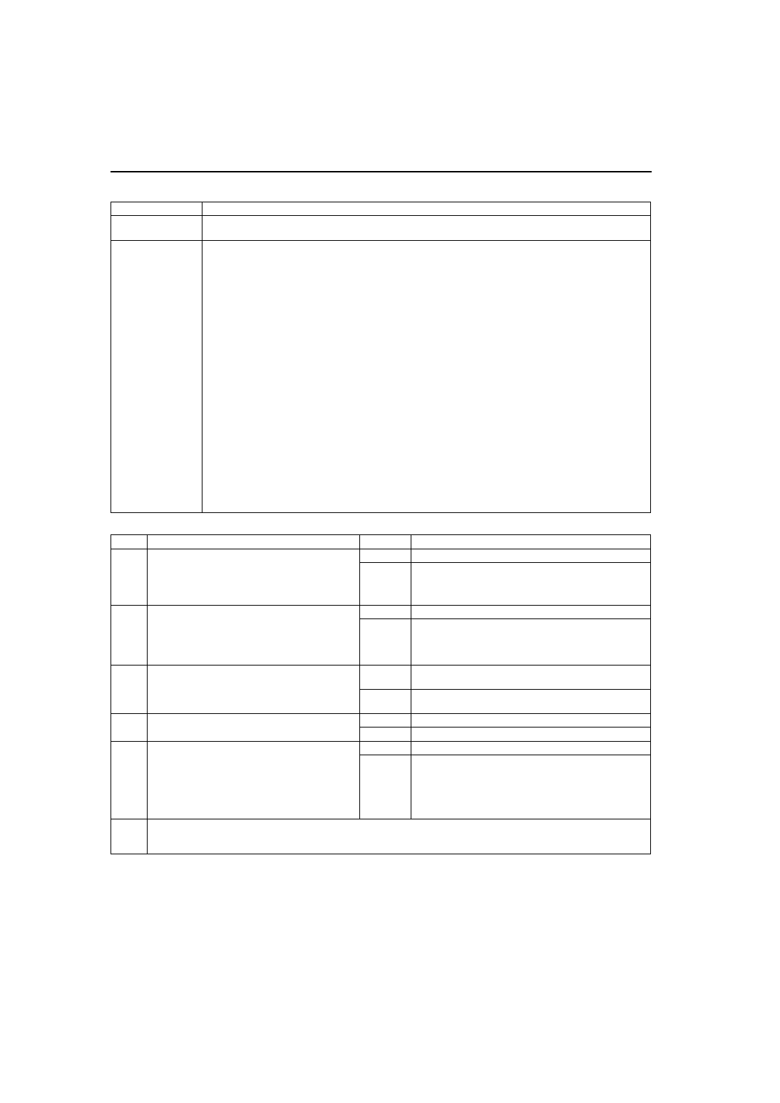
STEP
INSPECTION
RESULTS
ACTION
1
Connect WDS or equivalent to DLC-2.
Access ECT PID.
Verify ECT PID is less than 116
°C {241°F}
during driving.
Is ECT PID less than specification?
Yes
Go to next step.
No
Inspect cooling system for cause of overheating.
2
Connect WDS or equivalent to DLC-2.
Access IAT, MAF and SPARKADV PIDs.
Monitor each PID.
(See
.)
Are PIDs okay?
Yes
Go to next step.
No
IAT PID: Inspect IAT sensor
MAF PID: Inspect MAF sensor
SPARKADV PID: Inspect CMP sensor and knock
sensor.
3
Connect WDS or equivalent to DLC-2.
Retrieve any continuous memory, KOEO and
KOER DTCs.
Are there any DTCs displayed?
Yes
DTC is displayed:
Go to appropriate DTC test.
No
No DTC is displayed:
Go to next step.
4
Is engine compression correct?
Yes
Go to next step.
No
Inspect for cause.
5
Install fuel pressure gauge between fuel pipe
and fuel distributor.
Start engine and run it at idle.
Measure fuel line pressure at idle.
Is fuel line pressure correct at idle?
(See
Yes
Inspect ignition timing.
No
Zero or low:
Inspect for clogged fuel line.
If okay, replace fuel pump unit.
High:
Replace fuel pump unit.
6
Verify test results.
• If okay, return to diagnostic index to service any additional symptoms.
• If malfunction remains, replace PCM.