Mazda 6. Manual - part 121


  Index      Mazda     Mazda 6 - service repair manual 2002 year


Search            


Content   ..  119  120  121  122   ..


Mazda 6. Manual - part 121


F–20

FUEL SYSTEM 

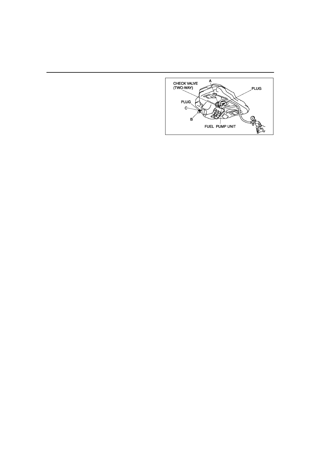
8. Turn the fuel tank upside-down and apply 

pressure of –2.0 kPa {–15 mmHg, –0.6 inHg} to 
port A.
(1) Plug port C and verify there is no vacuum 

from port B.

• If there is vacuum, replace the fuel tank.

End Of Sie

NONRETURN VALVE INSPECTION

A6E391242270W01

1. Remove the fuel pump unit. (See 

F–22 FUEL PUMP UNIT REMOVAL/INSTALLATION

.)

2. Siphon the fuel from the fuel tank.

Note

• Nonreturn valve is integrated in the fuel tank.

• The nonreturn valve is normally closed by the spring force.

3. Verify that the nonreturn valve is closed.

• If the nonreturn valve is stuck open and dose not open even when pulled up by a finger, replace the fuel 

tank.

End Of Sie

FUEL LINE PRESSURE INSPECTION

A6E391201006W03

Warning

• Fuel line spills and leakage are dangerous. Fuel can ignite and cause serious injuries or death. 

Fuel can also irritate skin and eyes. To prevent this, always complete the “BEFORE REPAIR 
PROCEDURE”. (See 

F–17 BEFORE REPAIR PROCEDURE

.)

Caution

• Disconnecting/connecting the quick release connector without cleaning it may possibly cause 

damage to the fuel pipe and quick release connector. Always clean the quick release connector 
joint area before disconnecting/connecting using cloth or soft brush, and make sure that it is free 
of foreign material.

1. Complete the “BEFORE REPAIR PROCEDURE”.

(See 

F–17 BEFORE REPAIR PROCEDURE

)

2. Disconnect the negative battery cable.

Caution

• The quick release connector may be damaged if the tab is turned too far. Do not turn the tab over 

the stopper.

3. Disconnect the quick release connector from the fuel tank as follows:

(1) Push the tab on the locking coupler 90 degrees until it stops.
(2) Pull the fuel hose straight back.

A6E3912W046

FUEL SYSTEM 

F–21

F

Note

• The stopper may be removed from the quick 

connector. Take care not to loose it. 
Reinstall it to the quick release connector 
before reconnecting the fuel line.

• The locking coupler has two internal locking 

tabs which retain the pulsation damper pipe. 
Be sure that the tab on the locking coupler is 
rotated until it stops to release two internal 
locking tabs.

4. Push the SST quick release connector into the 

fuel pipe and plastic fuel hose into the SST until a 
click is heard.

5. Turn the lever parallel to the hose of the SST as 

shown.

6. Connect the negative battery cable.
7. Verify that the vehicles for AT is at N range and 

MT is at neutral position.

8. Start the engine and let it idle. Measure the fuel 

line pressure.

• If not as specified, inspect the following:

Zero or low
— FP circuit
— FP
— Fuel line (clogged)
— Fuel leakage inside pressure regulator
High
— Pressure regulator for high pressure cause

Fuel line pressure

375—450 kPa {3.9—4.5 kgf/cm

2

, 55—65 psi}

9. Observe the fuel pressure gauge indicator during heavy acceleration.

10. Verify that the fuel pressure fluctuation is within the specification during the test.

• If not as specified, inspect the following: 

— PCM
— FP
— Pulsation damper
— Fuel line for improper routing, kinks or leakage

Fuel pressure fluctuation

365—450 kPa {3.8—4.5 kgf/cm

2

, 53—65 psi}

11. Turn the ignition switch to the LOCK position.
12. Measure the fuel hold pressure after 5 min.

• If not as specified, inspect the following:

— FP hold pressure
— Fuel injector for leakage
— Fuel line for improper routing, kinks or leakage

Fuel hold pressure

More than 200 kPa {2.0 kgf/cm

2

, 29 psi}

A6E3912W001

A6E3912W002

A6E3912W003

F–22

FUEL SYSTEM 

13. Complete the “BEFORE REPAIR PROCEDURE”.

(See 

F–17 BEFORE REPAIR PROCEDURE

)

14. Disconnect the SST.

Note

• A checker tab is integrated with quick release connector for new plastic fuel hoses. The checker tab will 

be released from the quick release connector after it is completely engaged with the fuel pipe.

15. Inspect the plastic fuel hose and fuel pipe sealing 

surface for damage and deformation, and replace 
as necessary.

• If the quick release connector O-ring is 

damaged or has slipped, replace the plastic 
fuel hose.

16. Apply a small amount of clean engine oil to the 

sealing surface of the fuel pipe.

17. Reconnect the fuel main hose to the fuel 

distributor until a click is heard.

18. Lightly pull and push the quick release connector 

a few times by hand and verify that it can move 
2.0—3.0 mm {0.08—0.11 in} and it is connected 
securely.

• If quick release connector does not move at all, verify that O-ring is not damaged and slipped, and 

reconnect the quick release connector.

19. Complete the “AFTER REPAIR PROCEDURE”. (See 

F–17 AFTER REPAIR PROCEDURE

.)

End Of Sie

FUEL PUMP UNIT REMOVAL/INSTALLATION

A6E391213350W01

Warning

• Fuel line spills and leakage are dangerous. Fuel can ignite and cause serious injuries or death and 

damage. Fuel can also irritate skin and eyes. To prevent this, do not damage the sealing surface of 
the fuel pump unit when removing or installing.

Caution

• Disconnecting/connecting the quick release connector without cleaning it may possibly cause 

damage to the fuel pipe and quick release connector. Always clean the quick release connector 
joint area before disconnecting/connecting using a cloth or soft brush, and make sure that it is 
free of foreign material.

1. Complete the “BEFORE REPAIR PROCEDURE”. (See 

F–17 BEFORE REPAIR PROCEDURE

.)

2. Disconnect the negative battery cable.
3. Remove the rear seat cushion.
4. Remove in the order indicated in the table.

.

5. Install in the reverse order of removal.
6. Complete the “AFTER REPAIR PROCEDURE”. 

(See 

F–17 AFTER REPAIR PROCEDURE

.)

A6E3912W004

1

Service hole cover

2

Connector

3

Plastic fuel hose
(See 

F–23 Plastic Fuel Hose Removal Note

)

(See 

F–24 Plastic Fuel Hose Installation Note

)

4

Fuel  pump  cap
(See 

F–23 Fuel Pump Cap Removal Note

)

5

Packing

6

Fuel pump unit
(See 

F–24 Fuel Pump Unit Installation Note

)

A6E3912W030

FUEL SYSTEM 

F–23

F

Plastic Fuel Hose Removal Note

Caution

• The quick release connector may be damaged if the tab is bent excessively. Do not expand the tab 

over the stopper.

1. Disconnect the quick release connector.

(1) Push the tab on the locking coupler 90 degrees until it stops.
(2) Pull the fuel hose straight back.

Note

• The stopper may be removed from the quick connector. Take care not to lose it.

Reinstall it to the quick release connector 
before reconnecting the fuel line.

• The locking coupler has two internal locking 

tabs which retain the fuel pipe. Be sure that 
the tab on the locking coupler is rotated until 
it stops to release two internal locking tabs.

2. Cover the disconnected quick release connector 

and fuel pipe with vinyl sheets or the like to 
prevent them from being scratched or 
contaminated with foreign material.

Fuel Pump Cap Removal Note

1. Using the SST, remove the fuel pump unit.

A6E3912W001

A6E3912W002

A6E3912W039

A6E3912W036


Content   ..  119  120  121  122   ..