Mazda 6. Manual - part 57
MULITIPLE COMMUNICATION SYSTEM
T–9
T
T
End Of Sie
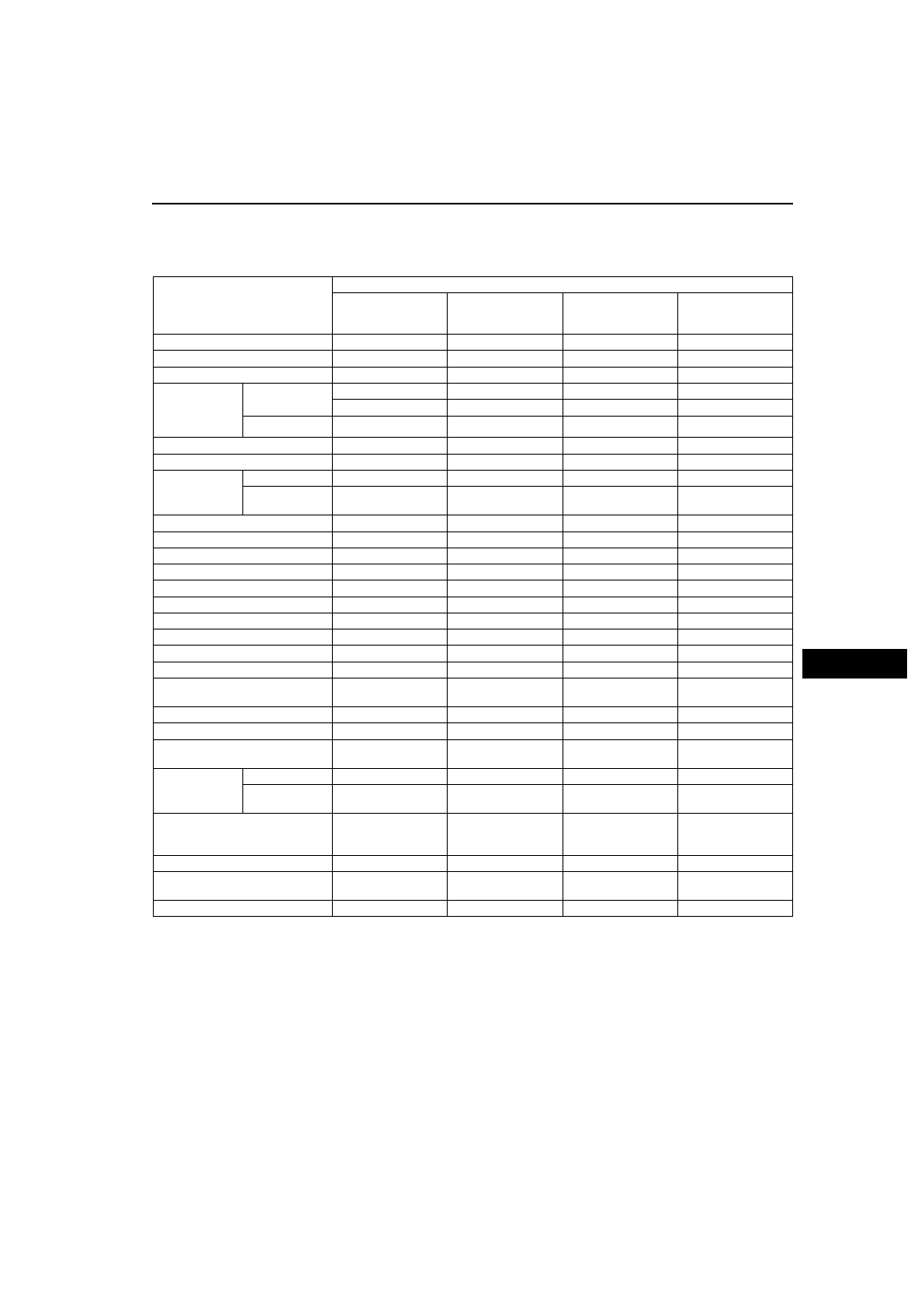
CAN SIGNAL-CHART
A6E811155430T08
OUT: Output (sends signal)
IN: Input (receives signal)
End Of Sie
Signal
Multiplex module
PCM
ABS (ABS/TCS) HU/
CM or DSC HU/CM
Instrument cluster
Audio unit
(information
display)
Engine condition
OUT
IN
Torque reduction inhibit
OUT
IN
Engine speed
OUT
IN
IN
Wheel speed
(front left/front
right/rear left/
rear right)
With ABS (ABS/
TCS) or DSC
IN
OUT
OUT
IN
Without ABS
OUT
IN
TP
OUT
IN
ECT
OUT
IN
Travelled
distance
—
IN
OUT
MTX, without
ABS
OUT
IN
Fuel injection amount
OUT
IN
MIL condition
OUT
IN
Generator warning light conditions
OUT
IN
Engine displacement
OUT
IN
Number of cylinders
OUT
IN
Air induction type
OUT
IN
Fuel type and delivery
OUT
IN
Country
OUT
IN
Transmission/axle type
OUT
IN
Tire circumference (front/rear)
OUT
IN
Desired gear/Change lever
position
OUT
IN
IN
HOLD switch conditions
OUT
IN
Torque reduction request
IN
OUT
Brake system configuration (EBD/
ABS/TCS/DSC)
IN
OUT
IN
Brake system
status
ABS
IN
OUT
EBD/ABS/TCS/
DSC
OUT
IN
Brake system warning light
conditions (brake fluid level
sensor)
IN
OUT
ABS configuration
IN
IN
OUT
Drive information system switch
operation
IN
OUT
Drive information system display
OUT
IN