Mazda Protege 5. Manual - part 198


  Index      Mazda     Mazda Protege 5 - service repair manual 2002 year


Search            


Content   ..  196  197  198  199   ..


Mazda Protege 5. Manual - part 198


DRIVE SHAFT 

03–13–16

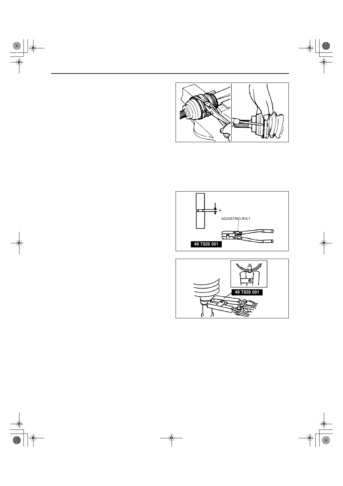
Boot Band (Transaxle Side) Assembly Note

1. Fold the band back and use pliers to pull it tight.

Note

Always use new bands.

The band should be folded in the direction 
opposite to the forward revolving direction of 
the drive shaft.

2. Lock the end of the band by bending the locking 

clips.

Caution

••••

Verify that the boot band is installed in 
the boot groove securely.

Boot Band (Wheel Side) Assembly Note

1. Adjust clearance A by turning the adjusting bolt of the SST.

Clearance A

2.9 mm {0.11 in}

2. Crimp the wheel side small boot band using the 

SST. Verify that clearance B is within the 
specification.

If clearance B is more than the specification, 
reduce clearance A of the SST and crimp the 
boot again.

If clearance B is less than the specification, 
replace the boot band, increase clearance A 
of the SST, and crimp the new boot.

Clearance B

2.4—2.8 mm {0.095—0.110 in}

3. Verify that the boot band does not protrude from 

the boot band installation area.

If it does, replace the boot band and repeat 
from Step 1.

4. Fill the boot with the repair kit grease.
5. Adjust clearance A by turning the adjusting bolt of 

the SST.

Clearance A

3.2 mm {0.13 in}

6. Crimp the wheel side big boot band using the SST.
7. Verify that clearance B is within the specification.

If clearance B is more than the specification, 
reduce clearance A of the SST and crimp the boot again.

If clearance B is less than the specification, replace the boot band, increase clearance A of the SST and 
crimp the new boot.

Clearance B

2.4—2.8 mm {0.095—0.110 in}

8. Verify that the boot band does not protrude from the boot band installation area.

If it does, replace the boot band and repeat from Steps 5.

End Of Sie

Y3E6316W035

Z3U0313W009

Y3E6316W028

1712-1U-01G(03-13).fm  16 ページ  2001年6月29日 金曜日 午前9時59分

DRIVE SHAFT 

03–13–17

03–13

DRIVE SHAFT (FS MTX LEFT SIDE) DISASSEMBLY/ASSEMBLY

A3U031325500W05

1. Disassemble in the order indicated in the table.
2. Assemble in the reverse order of disassembly.

.

A3U0313W005

1

Boot band (wheel side)
(See 03–13–12 DRIVE SHAFT (ZM, FS ATX, FS 
MTX RIGHT SIDE) DISASSEMBLY/ASSEMBLY)

2

Boot band (transaxle side)
(See 03–13–12 DRIVE SHAFT (ZM, FS ATX, FS 
MTX RIGHT SIDE) DISASSEMBLY/ASSEMBLY)

3

Clip
(See 03–13–18 Outer Ring Disassembly Note)
(See 03–13–19 Outer Ring, Clip Assembly Note).

4

Outer ring
(See 03–13–19 Outer Ring, Clip Assembly Note)

5

Snap ring
(See 03–13–19 Cage, Inner Ring, Balls, Snap Ring 
Assembly Note)

6

Balls
(See 03–13–18 Balls, Inner Ring, Cage 
Disassembly Note)
(See 03–13–19 Cage, Inner Ring, Balls, Snap Ring 
Assembly Note)

7

Inner Ring
(See 03–13–18 Balls, Inner Ring, Cage 
Disassembly Note)
(See 03–13–19 Cage, Inner Ring, Balls, Snap Ring 
Assembly Note)

8

Cage
(See 03–13–18 Balls, Inner Ring, Cage 
Disassembly Note)
(See 03–13–19 Cage, Inner Ring, Balls, Snap Ring 
Assembly Note)

9

Boot
(See 03–13–18 Boot Assembly Note)

10

Dynamic damper
(See 03–13–18 Dynamic Damper Assembly Note)

11

ABS sensor rotor
(See 03–13–12 DRIVE SHAFT (ZM, FS ATX, FS 
MTX RIGHT SIDE) DISASSEMBLY/ASSEMBLY)

12

Shaft and ball joint component

1712-1U-01G(03-13).fm  17 ページ  2001年6月29日 金曜日 午前9時59分

DRIVE SHAFT 

03–13–18

Outer Ring Disassembly Note

1. Mark the drive shaft and outer ring for proper 

assembly.

Caution

••••

Mark with paint; do not use a punch.

2. Remove the clip.

Balls, Inner Ring, Cage Disassembly Note

1. Mark the inner ring and cage.

Caution

••••

Mark with paint; do not use a punch.

2. Remove the snap ring using snap-ring pliers.
3. Turn the cage approximately 30 degree and pull 

the cage and balls away from the inner ring.

Dynamic Damper Assembly Note

1. Install the dynamic damper as shown in the 

figure.

Standard length

292—298 mm {11.5—11.7 in}

2. Install the new boot band onto the dynamic 

damper.

Boot Assembly Note

1. Fill the boot (wheel side) with the specified grease from a tube, not by hand.

Caution

••••

Do not touch grease with your hand. Apply it from the tube to prevent foreign matter from entering 
the boot.

Note

The wheel side and transaxle side boots are different.

Use the specified grease supplied in the boot kit.

Grease amount

 75—95 g {2.65—3.35 oz}

Z3U0313W005

YYJ6316W007

ZLU0313W141

1712-1U-01G(03-13).fm  18 ページ  2001年6月29日 金曜日 午前9時59分

DRIVE SHAFT 

03–13–19

03–13

2. With the splines of the shaft still wrapped in tape from disassembly, install the boot.
3. Remove the tape.

Cage, Inner Ring, Balls, Snap Ring Assembly Note

1. Align the marks and install the balls and cage to 

the inner ring in the direction shown in the figure.

Caution

••••

Install the cage with the offset facing the 
snap ring groove. If incorrectly installed, 
the drive shaft may become disengaged.

2. Install a new snap ring.

Outer Ring, Clip Assembly Note

1. Fill the outer ring and boot (transaxle side) with the specified grease.

Caution

••••

Do not touch grease with your hand. Apply it from the tube to prevent foreign matter from entering 
the boot.

Note

Use the specified grease supplied in the boot kit.

Grease amount

95—115 g {3.36—4.05 oz}

2. Align the marks, and install the outer ring on to the shaft.
3. Install a new clip.
4. Install the boot.
5. Set the drive shaft to the standard length.

Standard length

641.0—651.0 {25.24—25.62}

6. Release any trapped air from the boots by 

carefully lifting up the small end of each boot with 
a cloth wrapped screwdriver.

Caution

••••

Be careful not to allow the grease to leak.

••••

Do not damage the boot.

7. Verify that the drive shaft length is within the 

specification.

End Of Sie

Z3U0313W006

Y3E6316W033

1712-1U-01G(03-13).fm  19 ページ  2001年6月29日 金曜日 午前9時59分


Content   ..  196  197  198  199   ..