Range Rover 2. Electrical Manual - part 194
KEY INFORMATION
i
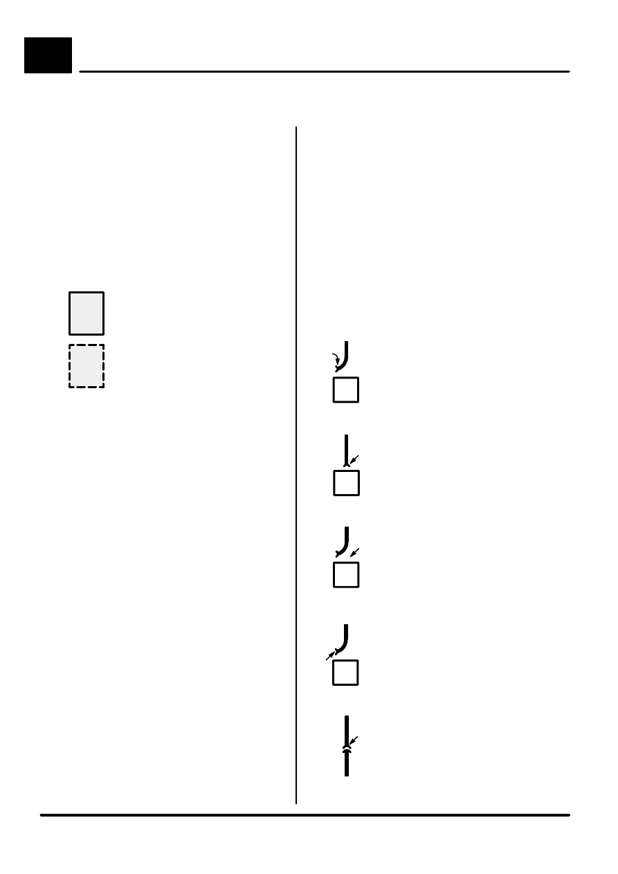
Component is disconnected.
Backprobe harness connector
Component is connected.
Backprobe harness connector
Component is disconnected.
Probe component
Component is disconnected.
Probe harness connector
Probe inĆline connector
TERMINAL
NUMBER
DESIGNATION
50
Battery voltage: Ignition Switch
in position III
30
Battery voltage: supplied constantly
15
Battery voltage: Ignition Switch
in position II or III
R
Battery voltage: Ignition Switch
in positions I, II
31
Ground
CIRCUIT DIAGRAMS
Circuit diagrams are arranged so that
current flow is from the top of the diagram
(current source) to the bottom of the
diagram (ground).
D
D Only those components that work together
in the circuit are shown. If only part of a
component is used in the circuit, then only
that part of the component is shown.
D Remember:
Entire component
Part of a component
D
DIAGNOSIS
If the diagram is accompanied by text:
- Read the Circuit Operation before
proceeding with the electrical diagnosis.
- Read the Troubleshooting Hints before
performing the System Diagnosis.
- Tests follow the System Diagnosis
- When performing the System Diagnosis,
be certain that all components
disconnected in previous steps are
reconnected unless otherwise directed.
See Introduction (i) for additional
circuit diagram symbols.