Land Rover Discovery. Manual - part 125


  Index      Land Rover     Land Rover Discovery - service 1995-1996 year


Search            


Content   ..  123  124  125  126   ..


Land Rover Discovery. Manual - part 125


FRONT AXLE AND FINAL DRIVE

1

REPAIR

FRONT AXLE ASSEMBLY

Service repair no - 54.15.01

Remove

WARNING: Remove and refit of axle
requires a further two persons to steady
axle when lowering or repositioning axle.

1. Support chassis front.
2. Remove road wheels.
3. Support axle weight with hydraulic jack.
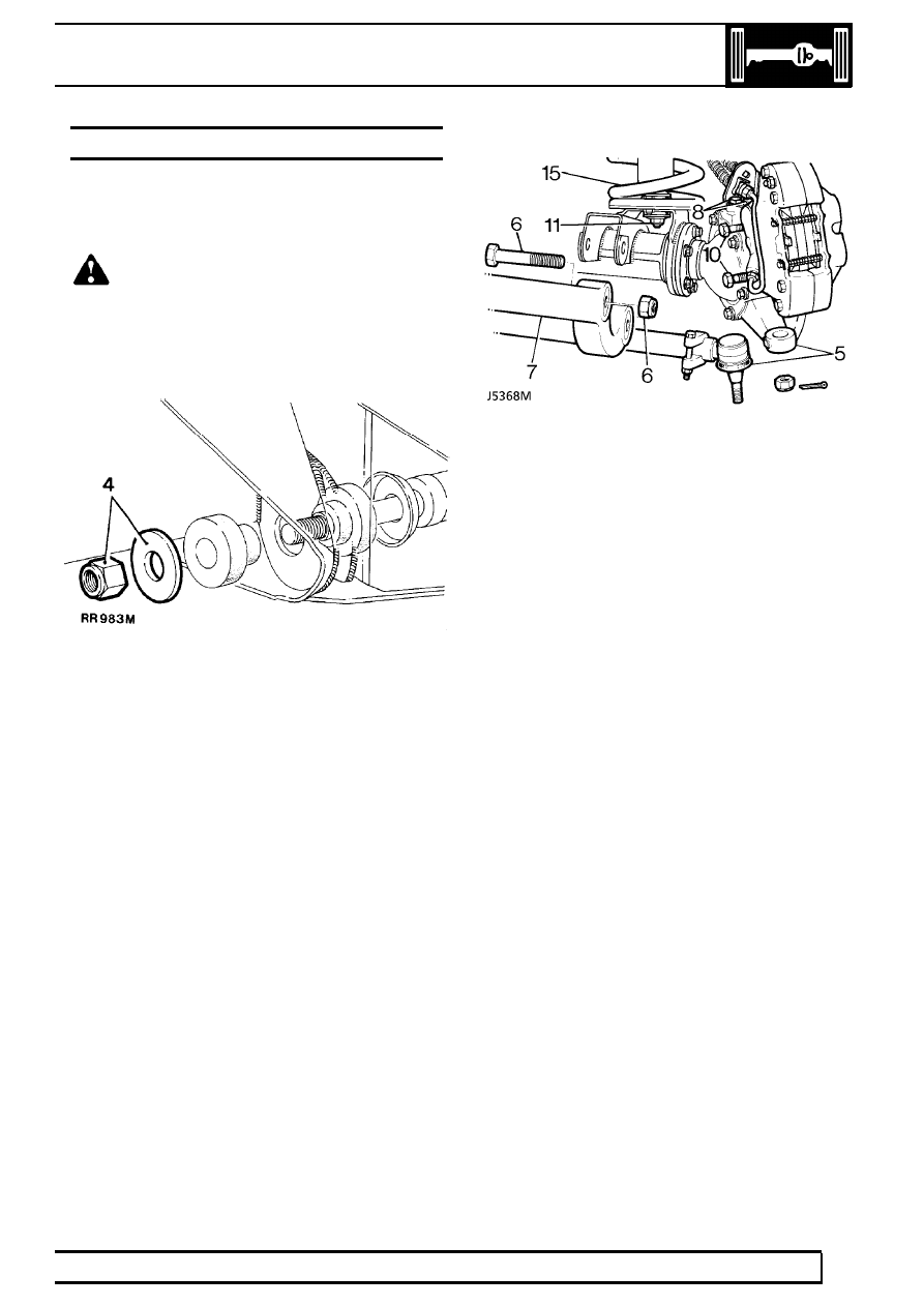
4. Remove radius arms to chassis frame nuts.

5. Disconnect steering damper from track rod.

Using a extractor remove track rod links from
swivel pin arms.

6. Remove four nuts and bolts securing radius

arms to axle bracket.

7. Remove radius arms.
8. Remove bolts securing brake hose brackets.

Refit bolts to prevent oil leakage.

9. Remove ABS sensor, if applicable.

10. Remove bolts from brake calipers and tie to one

side.

11. Remove nuts and washers securing shock

absorbers to axle.

12. Disconnect drag link from swivel pin housing

arm.

13. Remove two nuts and bolts securing panhard

rod to axle bracket. Lift rod clear of axle.

14. Mark for reassembly drive shaft flanges.

Remove four nuts and bolts, tie propeller shaft to
one side.

15. Lower axle assembly and remove road springs.
16. Disconnect anti-roll[sway] bar link.

See FRONT

SUSPENSION, Repair, Anti-Roll[Sway] Bar
Ball Joint Links

17. Remove axle assembly.

Refit

18. Position axle under vehicle, supporting left side

of axle.

19. Reverse removal procedure.
20. Tighten propeller shaft bolts to

47 Nm.

21. Tighten panhard rod to axle bracket to

88 Nm.

22. Tighten drag link to hub arm to

40 Nm.

23. Tighten upper swivel pin bolts.

See

Specifications, torque, Torque Values

24. Tighten radius arms to axle bolts to

197 Nm.

25. Tighten radius arms to chassis side member

nuts to

197 Nm.

26. Tighten track rod end to

40 Nm.

Fit new split [cotter] pin.

54

FRONT AXLE AND FINAL DRIVE

2

REPAIR

FRONT BRAKE DISCS

Service repair no - 70.10.10.

Remove

1. Remove front hub assembly.

See Front Hub

Assembly

2. Remove five hub to disc bolts.
3. Tap disc to separate from hub.

Refit

4. Locate disc to hub.
5. Apply Loctite 270 to disc bolts. Tighten to

73

Nm.

6. Check total disc runout with a dial indicator, this

must not exceed 0,15 mm. If necessary
reposition disc.

7. Fit hub assembly.

See Front Hub Assembly

Disc reclamation

8. Check disc thickness. This dimension may be

reduced to minimum thickness of 12 mm.
Machine equal amount off each face.

FRONT AXLE AND FINAL DRIVE

3

REPAIR

FRONT HUB ASSEMBLY

Service repair no - 60.25.01.

Remove

1. Loosen front wheel nuts, jack up vehicle and

lower onto axle stands and remove road wheel.

2. Release brake hose clips and remove brake

caliper. Secure to one side.

3. Lever off dust cap.
4. Remove circlip and drive shaft shim from

driveshaft.

5. Remove five bolts and withdraw driving member

and joint washer.

6. Bend back lock washer tabs.
7. Remove locknut and lock washer.
8. Remove hub adjusting nut.
9. Remove spacing washer.

10. Remove hub and brake disc assembly complete

with bearings.

HUB COMPONENTS

1. Dust cap.
2. Drive shaft circlip.
3. Drive shaft shim.
4. Drive member.
5. Drive member joint washer.
6. Drive member retaining bolt.
7. Lock nut.
8. Lock washer.
9. Hub adjusting nut.

10. Spacing washer.
11. Outer bearing.
12. Hub.
13. Inner bearing.
14. Grease seal.
15. Brake disc
16. Disc retaining bolt.

54

FRONT AXLE AND FINAL DRIVE

4

REPAIR

Refit

11. Clean stub axle and drive shaft and fit hub

assembly to axle.

12. Fit spacing washer.
13. Fit hub adjusting nut. Tighten to

61 Nm.

14. Back off adjusting nut 90

°

. Tighten to

4 Nm.

This will give the required hub end float of
0,010mm

15. Fit a new lock washer.

16. Fit locknut. Tighten to

61 Nm.

17. Tab over lock washer to secure adjusting nut

and locknut.

18. Fit a new joint washer to driving member and fit

member to hub and secure with five bolts.
Tighten to

65 Nm.

19. Fit original drive shaft shim and secure with a

circlip.

20. To check drive shaft end play mount a dial

gauge using bracket LRT-99-503 and rest pin in
a loaded condition on end of drive shaft.

21. Fit a suitable bolt to threaded end of drive shaft.

Move drive shaft in and out noting dial gauge
reading. End play should be between 0,08 to
0,25 mm.

22. If end play requires adjustment, remove circlip,

measure shim thickness and fit an appropriate
shim to give required end-play.

23. Remove bolt from drive shaft, fit circlip and dust

cap.

24. Fit brake caliper. Tighten to

82 Nm.

25. Bleed brake system.

See BRAKES, Repair,

Brake System Bleed

26. Fit road wheel, remove axle stands and tighten

road wheel nuts to

126 Nm.

27. Operate footbrake to locate brake pads before

taking vehicle on road.


Content   ..  123  124  125  126   ..