Content .. 1419 1420 1421 1422 ..
Jeep Liberty KJ. Manual - part 1421
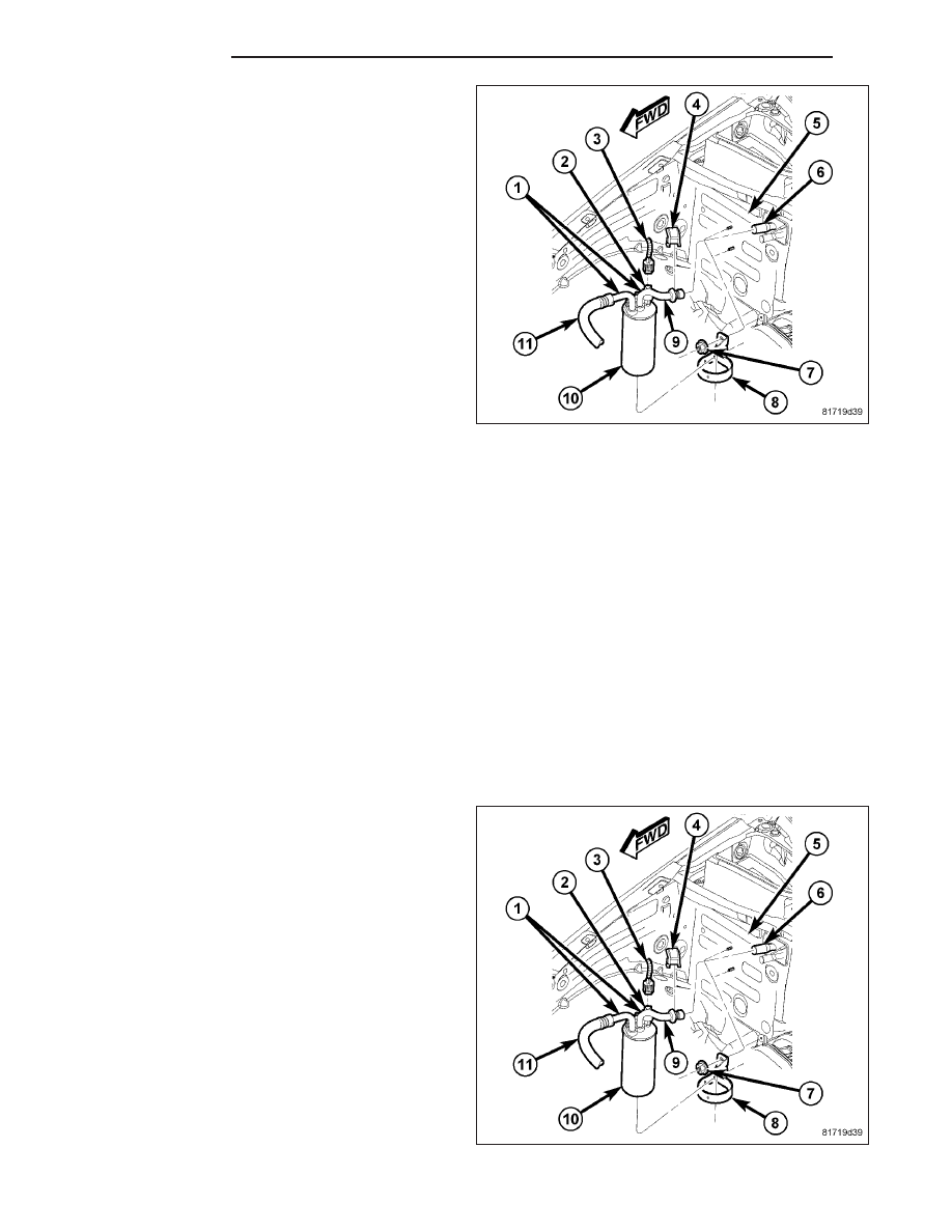
NOTE: LHD model shown. RHD model similar.
1. Disconnect and isolate the negative battery cable.
2. Recover the refrigerant from the refrigerant system
(Refer to 24 - HEATING & AIR CONDITIONING/
PLUMBING
-
STANDARD
PROCEDURE
-
REFRIGERANT SYSTEM RECOVERY).
3. Disconnect the wire lead and connector (3) from
the A/C low pressure switch (2) and remove the
switch from the A/C accumulator (10).
4. Remove the two nuts (7) that secure the accumu-
lator bracket (8) to the dash panel (5).
5. On LHD models, remove the secondary retaining
clip (4) from the suction line spring-lock coupler
and using the proper A/C line disconnect tool, dis-
connect the rear section of the A/C suction line (9)
from the evaporator outlet tube (6) (Refer to 24 -
HEATING
&
AIR
CONDITIONING/PLUMBING/
COUPLER-REFRIGERANT LINE - REMOVAL).
6. On RHD models, remove the nut that secures the rear section of the A/C suction line to the A/C evaporator and
disconnect the line from the evaporator.
7. Remove the nuts (1) that secure the rear section of the A/C suction line and the front section of the A/C suction
line (11) to the A/C accumulator and disconnect the lines from the accumulator.
8. Remove the A/C accumulator and the bracket from the engine compartment as an assembly and, if necessary,
remove the bracket from the accumulator.
9. Remove and discard the O-ring seals and install plugs in, or tape over the opened refrigerant line fittings and the
accumulator and evaporator ports.
INSTALLATION
NOTE: If the A/C accumulator is being replaced, add 120 milliliters (4 fluid ounces) of refrigerant oil to the
refrigerant system. Use only refrigerant oil of the type recommended for the A/C compressor in the vehicle.
NOTE: Replacement of the refrigerant line O-ring seals is required anytime a refrigerant line is opened. Fail-
ure to replace the rubber O-ring seals could result in a refrigerant system leak.
NOTE: LHD model shown. RHD model similar.
1. If removed, install the A/C accumulator (10) into the
accumulator bracket (8) and position the accumula-
tor and bracket into the engine compartment as an
assembly.
2. Remove the tape or plugs from all of the opened
refrigerant line fittings and the accumulator and
evaporator ports.
3. Lubricate new rubber O-ring seals with clean refrig-
erant oil and install them onto the refrigerant line
fittings. Use only the specified O-rings as they are
made of a special material for the R-134a system.
Use only refrigerant oil of the type recommended
for the A/C compressor in the vehicle.
4. Connect the A/C suction lines (9 and 11) to the A/C
accumulator and install the retaining nuts (1).
Tighten the nuts to 12.5 N·m (110 in. lbs.).
24 - 86
PLUMBING
KJ