Jeep Grand Cherokee WK. Manual - part 353
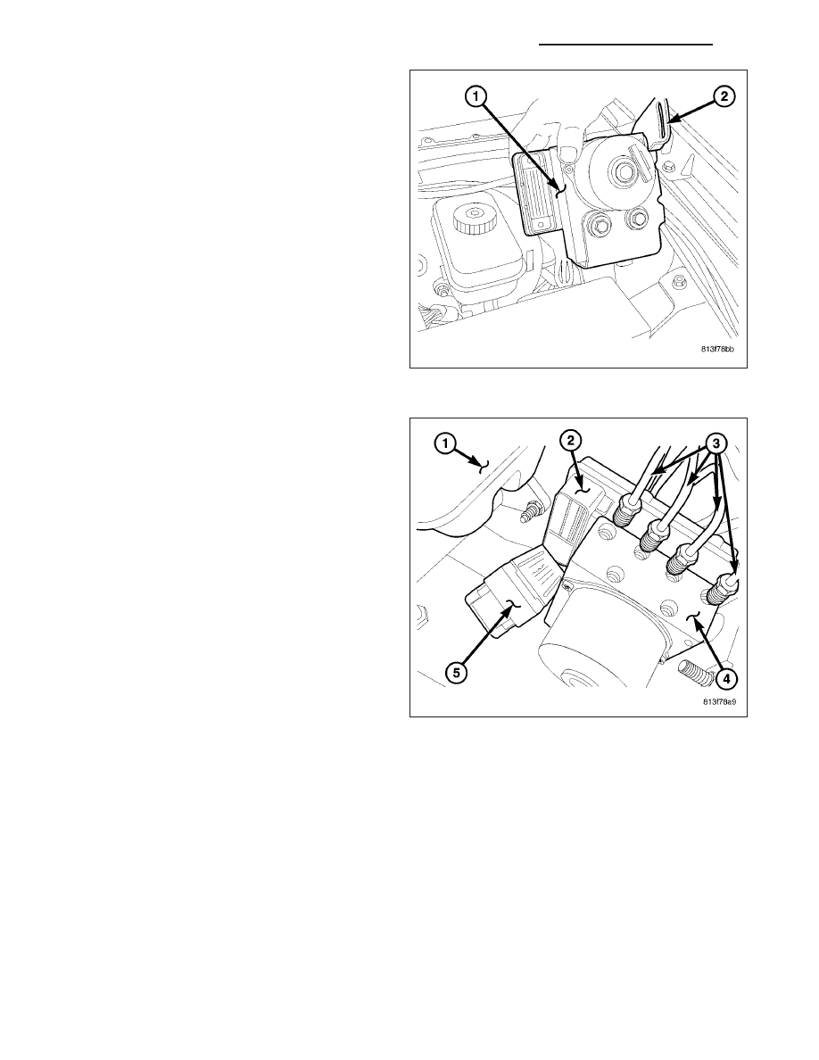
3. Install the HCU (1) with bracket (2) to the vehicle
and tighten the 2 mounting nuts.
4. Reconnect the HCU electrical connector (5).
5. Install the 4 chassis lines (3) at the HCU (4).
6. Install the secondary brake tube at the HCU (4).
7. Install the secondary brake tube at the master cyl-
inder.
8. Install the primary brake tube at the HCU (4).
9. Install the primary brake tube at the master
cylinder.
10. Install negative battery cable to the battery.
11. Remove the brake pedal prop rod.
12. Bleed base and ABS brake systems, (Refer to 5 - BRAKES - STANDARD PROCEDURE).
13. Initialize the ABS module using the scan tool.
COMMUNICATION
DESCRIPTION
The Controller Area Network (CAN) is a serial data bus communication network used for interconnecting numerous
electronic control modules throughout the vehicle in a two-wire multiplexed system. Within this context the term
serial refers to electronic data that is transferred bit by bit, while bus refers to the shared wires through which that
data is transferred. Multiplexing is any system that enables the transmission of multiple messages over a single
channel or circuit. The communication protocol being used is a non-proprietary, open standard adopted from the
Bosch CAN Specification 2.0b and uses an 11-bit message identifier.
8E - 258
ELECTRONIC CONTROL MODULES - SERVICE INFORMATION
WK