Jeep Grand Cherokee WK. Manual - part 1531


  Index      Jeep     Jeep Grand Cherokee WK - service repair manual 2005 year


Search            


Content   ..  1529  1530  1531  1532   ..


Jeep Grand Cherokee WK. Manual - part 1531


C140D- TRANSFER CASE MOTOR CONTROL CIRCUIT OPEN (CONTINUED)

For a complete wiring diagram Refer to Section 8W

When Monitored:
With the ignition on and no system undervoltage or overvoltage condition present.

Set Condition:
The Final Drive Control Module detects an open circuit on one of the Transfer Case Shift Motor Control cir-
cuits.

Possible Causes

INTERMITTENT TRANSFER CASE MOTOR CONTROL CIRCUIT OPEN

(T315) SHIFT MOTOR CONTROL A CIRCUIT OPEN

(T316) SHIFT MOTOR CONTROL B CIRCUIT OPEN

TRANSFER CASE MOTOR

FINAL DRIVE CONTROL MODULE

Diagnostic Test

1.

DTC IS ACTIVE

Ignition on, engine not running.

With the scan tool, select View DTCs.

Is the status Active for this DTC?

Yes

>> Go to 2

No

>> Go to 8

2.

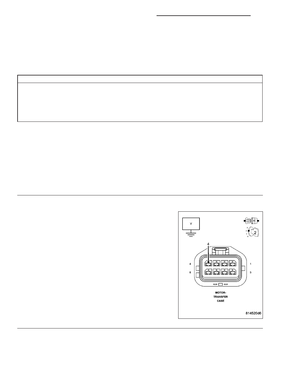
(T315) SHIFT MOTOR CONTROL A CIRCUIT VOLTAGE

Turn the ignition off.

Disconnect the Transfer Case Motor harness connector.

Ignition on, engine not running.

Measure the voltage of the (T315) Shift Motor Control A circuit at the
harness connector.

Is the voltage within 1 volt of battery voltage?

Yes

>> Go to 3

No

>> Go to 4

21 - 934

TRANSFER CASE - ELECTRICAL DIAGNOSTICS

WK

C140D- TRANSFER CASE MOTOR CONTROL CIRCUIT OPEN (CONTINUED)

3.

(T316) SHIFT MOTOR CONTROL B CIRCUIT VOLTAGE

Measure the voltage of the (T316) Shift Motor Control B circuit at the
harness connector.

Is the voltage within 1 volt of battery voltage?

Yes

>> Go to 6

No

>> Go to 5

4.

(T315) SHIFT MOTOR CONTROL A CIRCUIT OPEN

Turn the ignition off.

Disconnect the Final Drive Control Module C1 harness connector.

Measure the resistance of the (T315) Shift Motor Control A circuit from the Transfer Case Motor harness connector
to the Final Drive Control Module C1 harness connector.

Is the resistance above 5.0 ohms?

Yes

>> Repair the (T315) Shift Motor Control A circuit for an open.

Perform the TRANSFER CASE VERIFICATION TEST-VER 1.

No

>> Go to 7

5.

(T316) SHIFT MOTOR CONTROL B CIRCUIT OPEN

Turn the ignition off.

Disconnect the Final Drive Control Module C1 harness connector.

Measure the resistance of the (T316) Shift Motor Control B circuit from the Transfer Case Motor harness connector
to the Final Drive Control Module C1 harness connector.

Is the resistance above 5.0 ohms?

Yes

>> Repair the (T316) Shift Motor Control B circuit for an open.

Perform the TRANSFER CASE VERIFICATION TEST-VER 1.

No

>> Go to 7

WK

TRANSFER CASE - ELECTRICAL DIAGNOSTICS

21 - 935

C140D- TRANSFER CASE MOTOR CONTROL CIRCUIT OPEN (CONTINUED)

6.

TRANSFER CASE MOTOR

Using the wiring diagram/schematic as a guide, inspect all wiring and connectors that pertain to this circuit.

Were any problems found?

Yes

>> Repair as necessary.

Perform the TRANSFER CASE VERIFICATION TEST-VER 1.

No

>> Replace the Transfer Case Motor in accordance with the Service Information.

Perform the TRANSFER CASE VERIFICATION TEST-VER 1.

7.

FINAL DRIVE CONTROL MODULE

Using the wiring diagram/schematic as a guide, inspect all wiring and connectors that pertain to this circuit.

Were any problems found?

Yes

>> Repair as necessary.

Perform the TRANSFER CASE VERIFICATION TEST-VER 1.

No

>> Replace the Final Drive Control Module in accordance with the Service Information.

Perform the TRANSFER CASE VERIFICATION TEST-VER 1.

8.

INTERMITTENT WIRING AND CONNECTORS

The conditions necessary to set this DTC are not present at this time.

Using the wiring diagram/schematic as a guide, inspect the wiring and connectors.

While monitoring the scan tool data relative to this circuit, wiggle test the wiring and connectors.

Look for the data to change or for the DTC to reset during the wiggle test.

Were any problems found?

Yes

>> Repair as necessary.

Perform the TRANSFER CASE VERIFICATION TEST-VER 1.

No

>> Test complete.

21 - 936

TRANSFER CASE - ELECTRICAL DIAGNOSTICS

WK

C140E-TRANSFER CASE MOTOR BLOCKED

For a complete wiring diagram Refer to Section 8W

When Monitored:
With the ignition on and no system undervoltage or overvoltage condition present.

Set Condition:
The Final Drive Control Module is unable to engage the requested range.

Possible Causes

INTERMITTENT TRANSFER CASE MOTOR BLOCKED

TRANSFER CASE INTERNAL CONDITION

TRANSFER CASE MOTOR

FINAL DRIVE CONTROL MODULE

Diagnostic Test

1.

DTC IS ACTIVE

Ignition on, engine not running.

With the scan tool, select View DTCs.

Is the status Active for this DTC?

Yes

>> Go to 2

No

>> Go to 5

2.

TRANSFER CASE INTERNAL CONDITION

Turn the ignition off.

Inspect the Transfer Case in accordance with the Service Information to determine if there are any mechanical con-
ditions that are preventing the Shift Motor from engaging the requested range.

Are any mechanical conditions preventing the Shift Motor from engaging the requested range?

Yes

>> Repair or replace the Transfer Case in accordance with the Service Information.

Perform the TRANSFER CASE VERIFICATION TEST-VER 1.

No

>> Go to 3

3.

TRANSFER CASE MOTOR

Turn the ignition off.

Using the wiring diagram/schematic as a guide, inspect all wiring and connectors that pertain to this circuit.

If any problems are found, repair as necessary and retest.

If no other problems are found, replace the Transfer Case Motor in accordance with the Service Information.

Ignition on, engine not running.

Cycle the Transfer Case Selector Switch to each position several times during a test drive.

With the scan tool, select View DTCs.

Is the DTC status Active?

Yes

>> Go to 4

No

>> Test complete.

Perform the TRANSFER CASE VERIFICATION TEST-VER 1.

WK

TRANSFER CASE - ELECTRICAL DIAGNOSTICS

21 - 937


Content   ..  1529  1530  1531  1532   ..