Content .. 1166 1167 1168 1169 ..
Jeep Grand Cherokee WK. Manual - part 1168
1. Start the engine.
2. Spray a small stream of water (spray bottle) at the suspected leak area.
3. If engine RPM’S change, the area of the suspected leak has been found.
4. Repair as required.
REMOVAL
1. Perform the Fuel System Pressure Release procedure (Refer to 14 - FUEL SYSTEM/FUEL DELIVERY - STAN-
DARD PROCEDURE).
2. Disconnect negative cable from battery.
3. Remove resonator assembly and air inlet hose.
4. Disconnect throttle and speed control cables.
5. Disconnect electrical connectors for the following components: Refer to FUEL SYSTEM for component locations.
•
Manifold Absolute Pressure (MAP) Sensor
•
Intake Air Temperature (IAT) Sensor
•
Throttle Position (TPS) Sensor
•
Coolant Temperature (CTS) Sensor
•
Idle Air Control (IAC) Motor
6. Disconnect vapor purge hose, brake booster hose, speed control servo hose, positive crankcase ventilation
(PCV) hose.
7. Remove the generator.
8. Remove the air conditioning compressor.
9. Disconnect left and right radio suppressor straps.
10. Disconnect and remove ignition coil towers.
11. Remove top oil dipstick tube retaining bolt and ground strap.
12. Remove fuel rail.
13. Remove throttle body assembly and mounting
bracket.
14. Drain cooling system below coolant temperature
level (Refer to 7 - COOLING - STANDARD PRO-
CEDURE).
15. Remove the heater hoses from the engine front
cover and the heater core.
16. Unclip and remove heater hoses and tubes from
intake manifold.
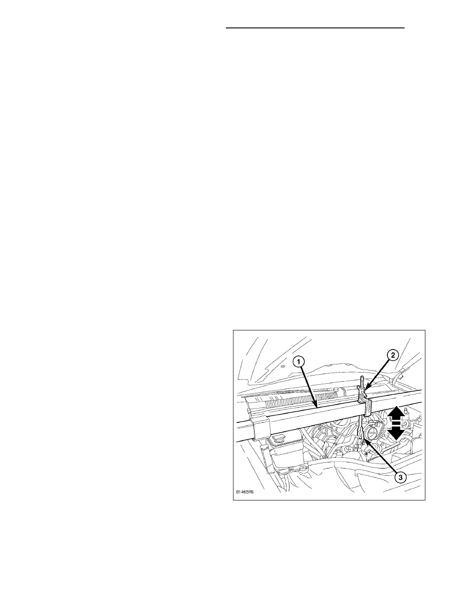
17. Support engine using engine support fixture (1),
special tool # 8534.
9 - 1268
ENGINE - 3.7L SERVICE INFORMATION
WK