Jeep Grand Cherokee WK. Manual - part 43


  Index      Jeep     Jeep Grand Cherokee WK - service repair manual 2005 year


Search            


Content   ..  41  42  43  44   ..


Jeep Grand Cherokee WK. Manual - part 43


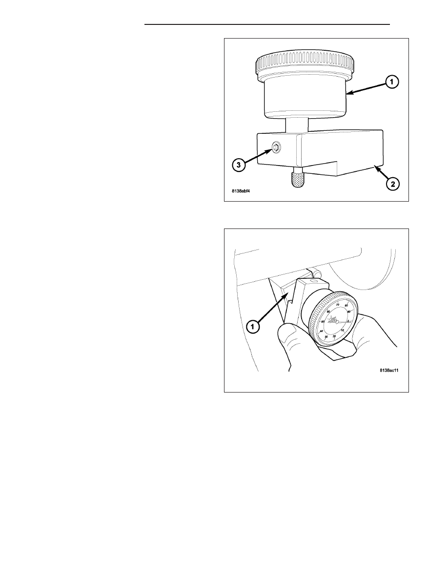
6. Install Dial Indicator 9524 (1) to Scooter Block

D-115-2A (2). Secure with set-screw (3).

7. Install Indicator/Block assembly to top of Height

Block 6739 (1). Zero indicator on top surface.

3 - 70

FRONT AXLE - C200F

WK

8. Slide indicator probe off of height block and onto

Arbor Bar D-115-3 (2). As indicator contacts Arbor
Bar (2), indicator needle will rotate clockwise. Con-
tinue moving indicator probe to the crest of the
arbor bar and record the highest reading. Then add
4 mm (0.157 in.) to the recorded reading. This will
give you the correct shim selection for pinion
height.

DIFFERENTIAL SIDE BEARING PRELOAD

Differential side bearing preload is predetermined. The select snap rings in the differential housing will provide the
correct differential side bearing preload. These snap can be adjusted to obtain the correct ring gear backlash mea-
surement.

RING GEAR BACKLASH MEASUREMENT

NOTE: If Spreader W-129-B is installed, make sure
tension on axle housing is relieved.

1. Set up Dial Indicator Set C-3339-A with Clamp

SP-5426 (1), Post SP-5425-B (2) and Metric Dial
Indicator 9524 (3) to measure ring gear backlash:

2. Rotate ring gear one direction to take up clearance

to pinion. Verify indicator tip is in contact with ring
gear and zero indicator. Rotate ring gear back and
forth and record measurement. Ring gear backlash
should be 0.13-0.18 mm (0.005-0.007 in.). Verify
back lash measurement in four (4) positions.

WK

FRONT AXLE - C200F

3 - 71

3. If backlash measurement is less than 0.13 mm

(0.005 in.), it is necessary to decrease the snap
ring thickness on the ring gear side, and increase
the thickness on the pinion side equal amounts.

4. If backlash measurement is greater than 0.18 mm

(0.007 in.), it is necessary to increase the snap ring
thickness on the ring gear side, and decrease the
thickness on the pinion side equal amounts.

GEAR CONTACT PATTERN

The ring gear and pinion teeth contact patterns will show if the pinion depth is correct in the housing. It will also
show if the ring gear backlash has been adjusted correctly. The backlash can be adjusted within specifications to
achieve desired tooth contact patterns.

1. Apply a thin coat of hydrated ferric oxide or equivalent to the drive and coast side of the ring gear teeth.

2. Wrap, twist, and hold a shop towel around the pinion yoke to increase the turning resistance of the pinion. This

will provide a more distinct contact pattern.

3. With a boxed end wrench on a ring gear bolt, rotate the differential case one complete revolution in both direc-

tions while a load is being applied from shop towel.

The areas on the ring gear teeth with the greatest degree of contact against the pinion teeth will squeegee the
compound to the areas with the least amount of contact. Note and compare patterns on the ring gear teeth to Gear
Tooth Contact Patterns chart and adjust pinion depth and gear backlash as necessary.

3 - 72

FRONT AXLE - C200F

WK

Gear Tooth Contact Patterns

WK

FRONT AXLE - C200F

3 - 73


Content   ..  41  42  43  44   ..