Jaguar X-Type Sedan and Estate (Wagon). Manual - part 243


  Index      Jaguar     Jaguar X-Type Sedan and Estate (Wagon) (2.0 L, 2.5 L and 3.0 L Gasoline; 2.0 L and 2.2 L, Diesel) - manual 2001-2009 year


Search            


Content   ..  241  242  243  244   ..


Jaguar X-Type Sedan and Estate (Wagon). Manual - part 243


Published: 11-May-2011

Engine Cooling - 2.0L NA V6 - AJV6/2.5L NA V6 - AJV6/3.0L NA V6 - AJ27 - Engine
Cooling

Description and Operation

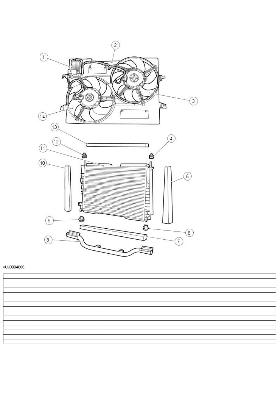
Cooling Module Components

Item

Part Number

Description

1

Cooling fan motor control module

2

Cooling fan shroud

3

Cooling fan, R/H

4

Radiator upper isolator mounting

5

Radiator side seal

6

Radiator lower isolator mounting

7

Radiator lower seal

8

Radiator support beam

9

Radiator lower isolator mounting

10

Radiator side seal

11

Radiator

12

Radiator upper isolator mounting

13

Radiator upper seal

14

Cooling fan, L/H

Engine Cooling System Components

Item

Part Number

Description

1

Upper coolant hose

2

Water pump

3

Coolant expansion tank

4

Coolant pressure cap

5

Thermostat

6

Engine oil cooler

7

Engine block heater (cold climate market vehicles only)

8

Engine block drain plug

• W ARNINGS:

 Never remove the coolant pressure cap under any circumstances while the engine is operating. Failure to follow this instruction may

result in personal injury.

To avoid having scalding hot coolant or steam blow out of the cooling system, use extreme care when removing the coolant pressure cap
from a hot cooling system. Wait until the engine has cooled, then wrap a thick cloth around the coolant pressure cap and turn it slowly until
the pressure begins to release. Step back while the pressure is released from the system. When certain all the pressure has been released
(still with a cloth) turn and remove the coolant pressure cap from the coolant expansion tank. Failure to follow these instructions may result
in personal injury.

 To avoid the possibility of personal injury, do not operate the engine with the hood open until the fan blades have been examined for

cracks and separation. Failure to follow this instruction may result in personal injury.

 Remove fuse 37 from the engine compartment fuse box prior to performing any under hood service in the area of the cooling fans

when the engine is hot, since the cooling fan motors could operate if the engine has been switched OFF. Failure to follow this instruction
may result in personal injury.

• CAUTIONS:

 The engine cooling system must be maintained with the correct concentration and type of anti-freeze solution to prevent corrosion

and frost damage.

 Never remove the coolant pressure cap under any circumstances while the engine is operating. Failure to follow this instruction may

result in damage to the engine.

The cooling system consists of the following:

Water pump.
Thermostat.
Radiator.
Coolant expansion tank.
Coolant pressure cap.
Two electric cooling fans.
Cooling fan motor control module.
Engine oil cooler.

Water Pump

The water pump is of a conventional design and is located at the rear of the engine. It is driven by the L/H exhaust camshaft through the
water pump drive pulley and belt. The water pump belt tension is maintained by an automatic drive belt tensioner. For additional
information, refer to Section

 303-05 Accessory Drive

.

Thermostat

The thermostat is located in a housing in the upper coolant hose and allows rapid engine warm-up by restricting coolant flow through the
radiator below 82°C (180°F). The thermostat also assists in keeping the engine operating temperature within predetermined limits. The
thermostat begins to open at 82°C (180°F) and is fully open at 93°C (199°F).

When the engine is cold and the thermostat is closed, coolant flows from the water pump through the engine. It then returns to the water
pump through the upper coolant hose.

When the engine is warm and the thermostat is open, coolant flows into the radiator through the upper coolant hose. It then returns to the
water pump from the radiator through the lower coolant hose and engine oil cooler.

The heater core is on a parallel circuit and is unaffected by the position of the thermostat.

Radiator

The radiator is of aluminium construction with plastic end tanks. Foam seals are fitted to the radiator to prevent the cooling air from by
passing the radiator core. The radiator is located by four isolator mountings and supported by the radiator support beam. A coolant drain
plug is provided in the lower coolant hose for the draining of the coolant. The Cooling fan shroud is attached to the radiator.

Cooling Fans

Two variable speed electric cooling fans are housed in the cooling fan shroud for the cooling of the radiator. The speed of the electric
cooling fans are adjusted by the cooling fan motor control module, which is controlled by the engine control module (ECM).

The ECM determines the cooling fan speed by receiving inputs from the engine coolant temperature (ECT) sensor and the dual automatic
temperature control module (DATC). The ECM sends a variable pulse width modulated (PWM) signal to the fan motor control module to
operate the cooling fans at the required speed. The cooling fans are operated at slow speed when the engine coolant temperature is at
95°C (203°F) and are operated at full speed when the engine coolant temperature is at 105°C (221°F). A coolant temperature between
these temperatures will cause the cooling fans to be operated at a speed which is proportional to the engine coolant temperature.

When the engine is running with the ECT above 100°C (212°F), if the ignition switch is turned to the OFF position the cooling fans will
continue to operate for a time which is determined by the ECM.

If the PW M signal from the ECM to the cooling fan control module is between 7% and 95% the cooling fan control module will operate the
cooling fans at the required speed. If the PWM signal from the ECM to the cooling fan control module is below 3% and above 95% the
cooling fan control module will operate the cooling fans at maximum speed. If the PWM signal from the ECM to the cooling fan control
module is between 3% and 7% the cooling fans will not be operated.

Engine Block Heater

For vehicle markets subject to very cold climate conditions, an engine block heater for connection to an external mains power supply, is
fitted in place of the engine block drain plug.

Coolant Recovery System

A pressurized coolant expansion tank system is used which continuously separates the air from the cooling system and replenishes the
system through the coolant expansion tank outlet hose, attached to the heater return hose.

A continuous vent from the engine and radiator to the coolant expansion tank prevents air locks from forming in the cooling system.

No manual bleed points are provided on the system.

The coolant expansion tank serves as the location for:

Service fill.

Coolant expansion during warm-up.
Air separation during operation.
System pressurization by the coolant pressure cap.
The coolant expansion tank is designed to have approximately 0.5 to 1 liter of air when cold to allow for coolant expansion.

Engine Oil Cooler

The engine oil cooler is a Modine oil to water type. The oil cooler is fitted between the oil filter housing and the oil filter and is a full flow
system.

The coolant supply for the engine oil cooler is through the radiator bottom hose.

Coolant Flow Diagram (Thermostat open)

Item

Part Number

Description

1

Engine

2

Throttle body

3

Expansion tank

4

Heater core

5

Water pump

6

Thermostat

7

Engine oil cooler

8

Radiator

Engine Coolant

The long life engine coolant is formulated to last for five years or 240,000 km (150,000 miles). The coolant is silicate free and orange in
color. The long life engine coolant must not be mixed with conventional engine coolant.


Content   ..  241  242  243  244   ..