Jaguar X-Type Sedan and Estate (Wagon). Manual - part 229


  Index      Jaguar     Jaguar X-Type Sedan and Estate (Wagon) (2.0 L, 2.5 L and 3.0 L Gasoline; 2.0 L and 2.2 L, Diesel) - manual 2001-2009 year


Search            


Content   ..  227  228  229  230   ..


Jaguar X-Type Sedan and Estate (Wagon). Manual - part 229


104. 

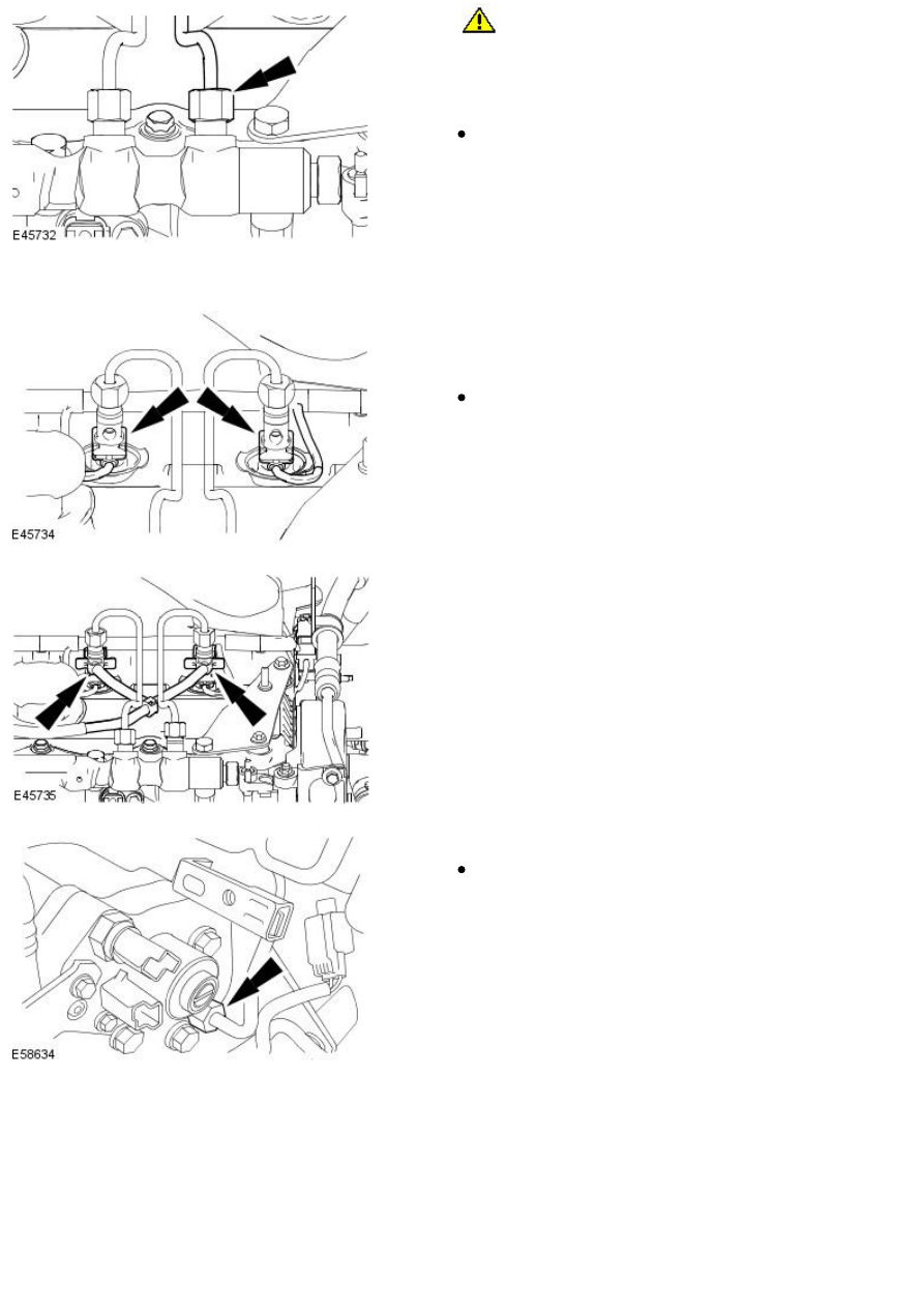
CAUTION: Make sure the tool used to tighten the high-pressure

fuel supply line unions is used at the top of the union as this is where
there is most material. Failure to follow this instruction may result in
damage to the union.

Tighten the high-pressure fuel supply line union at the fuel injection
supply manifold.

Tighten to 40 Nm.

105. Repeat steps 97, 98 and 99 for tightening the three remaining

high-pressure fuel supply line unions.

106. NOTE: Cylinders three and four fuel injectors shown, cylinders one
and two fuel injectors similar.

• NOTE: Install new O-ring seals.

Install the wiring harness.

Connect the fuel injector electrical connectors.

107. NOTE: Cylinders three and four fuel injectors shown, cylinders one
and two fuel injectors similar.

• NOTE: Install new O-ring seals.

Connect the fuel return lines to the fuel injectors.

108. Tighten the high pressure fuel supply line union at the fuel injection

supply manifold.

Tighten to 40 Nm.

109. 

CAUTION: Make sure the tool used to tighten the high pressure

fuel supply line union is used at the top of the union as this is where
there is most material. Failure to follow this instruction may result in
damage to the union.

Tighten the high pressure fuel supply line union at the fuel injection
supply manifold.

Tighten to 40 Nm.

110. Tighten to 8 Nm.

111. NOTE: Remove the blanking plugs from the fuel injector to fuel pump
fuel return line male and female connectors.

Connect the fuel injector to fuel pump fuel return line and attach the
line to the retaining clip.

112. Connect the fuel metering valve and fuel temperature sensor

electrical connectors.

113. Attach the mass air flow (MAF) sensor wiring harness.

114. Connect the camshaft position (CMP) sensor electrical connector.

115. Connect the cylinder head temperature (CHT) sensor electrical

connector.

116. Attach the CHT sensor electrical connector.

117. Install the exhaust manifold.

Tighten to 40 Nm.

118. Install the exhaust gas recirculation (EGR) cooler mount bracket.

Tighten to 10 Nm.

119. Install the EGR cooler mount bracket retaining bolt.

Tighten to 10 Nm.

120. NOTE: Install a new O-ring seal.

Install the oil return tube.

Tighten to 10 Nm.

121. NOTE: Install a new gasket.

Connect the oil return tube to the turbocharger.

Tighten to 10 Nm.

122. Install the oil supply tube.

Tighten to 14 Nm.

123. Attach the oil supply tube.

Tighten to 23 Nm.


Content   ..  227  228  229  230   ..