Engine JAC HFC4DA1-2C. Manual - part 158


  Index      JAC     Engine JAC HFC4DA1-2C - service repair manual


Search            


Content   ..  156  157  158  159   ..


Engine JAC HFC4DA1-2C. Manual - part 158


PS

PS

PS

PS PowerSteering

PowerSteering

PowerSteering

PowerSteering System

System

System

System

- 156 -

returnability between the left and right side.
It is necessary to carry out this step on safe ground
and under safe traffic condition and pay attention to
your safety.

Turn the steering wheel for 90°, drive with the
speed of 35Km/h, maintain the state for several
seconds and then release the steering wheel, the
returnability should be 70% at least.
Notice:

Notice:

Notice:

Notice:

In the case of rapid turning of the steering wheel,
there may be a transient feel of “arduous”due to
insufficient oil supply during idling and it is not a
fault.

6.

Inspection of Front Wheel Steering Angle

After the inspection of front wheel toe-in, inspect
the steering angle of the front wheel. Place the
front wheel on the steering angle measuring device
(front wheel alignment steering wheel) and inspect
the maximum steering angles of inner and outer
wheels on the left and right.
Inner Wheel:
Outer Wheel:

In the case of engine idling, make full lock turns of
the steering wheel to the left and right to measure
the steering angle.
If the measured value is not in the standard range,
adjust the tie rod.
The adjustment of the steering angle is as follows:
When the steering angle exceeds the standard value,
loosen lock nuts of the left and right steering tie
rods, rotate the left and right steering tie rods
respectively with a wrench to adjust the steering
angles to the standard values and then tighten the
lock nuts with a tightening torque of 45 ~ 55N.m.
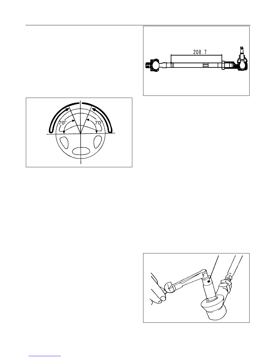
In the length adjustments of the left and right
steering tie rods (length shown in the following
figure), pay attention to adjust them to the same
value for the left and right steering tie rods
(208.7mm,in reversed directions)

Notice:

Notice:

Notice:

Notice:

When the steering angle of the inner wheel exceeds
the standard value, adjust the tie rod at this side to
rotate outward and the steering angle of the inner
wheel will increase; When the steering angle of the
outer wheel exceeds the standard value, adjust the
tie rod at this side to rotate outward and the
steering angle of the outer wheel will decrease.
Notice:

Notice:

Notice:

Notice:

The adjustment of the toe-in is interrelated with
those of the wheel alignment parameters and the
steering angle.

7.

Inspection of Ball Joint Dust Boot

Press the dust boot with hand to inspect it for crack
or damage.

In the case of cracked or damaged dust boot, it is
necessary to replace the tie rod ball joint.
Notice:

Notice:

Notice:

Notice:

In the case of cracked or damaged dust boot, the
ball joint may be damaged jointly.

8.

Inspection for Angular Moment of Steering Tie
Rod Ball Joint

Swing the tie rod rapidly for 10 times.

Measure the swing resistance of the tie rod with a
spring scale.
Standard value: 2~5 N.m
If the measured value is not in the range of
standard value, please replace it.

PS

PS

PS

PS PowerSteering

PowerSteering

PowerSteering

PowerSteering System

System

System

System

- 157 -

Inspection and Replacement of Steering Mechanism
Parts:
Inspection of Rack Piston Assembly:
Inspect the straightness accuracy for the intermediate
rack of the rack piston assembly and the maximum
deviation is 0.15mm. Inspect the tooth face for
exfoliation and impression, verify whether there are
cracks or damages on the operating surface of the tooth
and inspect the back of the tooth for wear and damage.
If necessary, replace the rack piston assembly. Inspect
the piston ring and o-ring in the piston for damages. In
the case of defects in them, it is necessary to carry out
replacement. In the replacement, remove the piston ring
and o-ring with a flat-blade screwdriver.

Notice:

Notice:

Notice:

Notice:

Pay attention not to damage the rack. Apply some power
steering hydraulic oil on the new o-ring and install the
o-ring.
Notice:

Notice:

Notice:

Notice:

Pay attention not to expand the piston ring excessively.
Install the new piston ring onto the piston of the rack
piston assembly, apply some power steering hydraulic
oil on the new piston ring and press it out downward
with fingers.
Inspection of Valve Assembly
Inspect the gear shaft tooth surface of the spool
assembly

for

cracks,

damages,

exfoliations

or

deformations. Inspect it for its flexible rotation, in the
case of any defects, replace the spool assembly.
Steering Column
Figure for Steering Column Assembly:

Schematic Diagram of Steering Column Assembly
1.

Horn hood with airbag

2.

Steering wheel

3.

Steering column assembly

4.

Connecting shaft with universal joint

5.

Protective cover

6.

Free

upward and downward adjustment

and

locking device of the steering wheel

Inspection of Steering Column:

Inspect

the

steering

column

for

cracks,

deformations or other damages, in the case of such
defects, carry out relevant replacement.

Inspect the spline of steering column shaft for wear
or broken tooth, in the case of such defects, carry
out relevant replacement.

Original Figure of Power-assisted Steering Gear Box

Notice:

Notice:

Notice:

Notice:

In the case of separation of the steering column and
steering gear assembly, rotation of steering wheel may
lead to clock spring damage. Therefore, it is necessary
to fix the steering wheel to prevent it from rotation.

Power-assisted Steering Gear Box
Inspect the oil pipe joint for looseness and
damages.
Inspect the fixed bush of the power steering gear
for wears or other damages.
Inspect the rack and pinion for their smooth
operations and wears.
Inspect the gear preload.
a.

Rotate the gear with the speed of 4~6 seconds
per turn and measure the gear preload in the
whole travel range of the rack.
Standard value: 0.6~1.3N.m

b.

If the measured value exceeds the specified
value, adjust the plug

firstly

and then

reinspect the gear preload.

c.

If the specified gear preload can not achieved
after plug adjustment, inspect or replace the
plug assembly.

Steering Tie Rod
Inspect the angular moment of steering tie rod.
a.

Swing the tie rod rapidly for 10 times.

b.

Measure the swing resistance of the tie rod
with a spring scale.
Standard value: 2~5 N.m
If the measured value is not in the range of
standard value, please replace it.
Notice:

Notice:

Notice:

Notice:

In the case of no excessive clearance of the tie
rod under the slow swing condition, even
though the measured value is lower than the
standard value, the tie rod can be applicable.
If the measured value is lower than 4.3N.m, it

PS

PS

PS

PS PowerSteering

PowerSteering

PowerSteering

PowerSteering System

System

System

System

- 158 -

is necessary to replace the tie rod.

Tie Rod Dust Boot

Inspect the dust boot for damage, in the case of
such defect, please carry out replacement.
Inspect the dust boot for its correct mounting
position.
Post-installation Inspection
Make full lock turns of the steering wheel to the
left and right for several times to verify its flexible
operation.

Inspection

Inspection

Inspection

Inspection and

and

and

and Replacement

Replacement

Replacement

Replacement of

of

of

of Steering

Steering

Steering

Steering Mechanism

Mechanism

Mechanism

Mechanism

Parts

Parts

Parts

Parts::::

Inspection of Rack Piston Assembly:
Inspect the straightness accuracy for the intermediate
rack of the rack piston assembly and the maximum
deviation is 0.15mm. Inspect the tooth face for
exfoliation and impression, verify whether there are
cracks or damages on the operating surface of the tooth
and inspect the back of the tooth for wear and damage.
If necessary, replace the rack piston assembly. Inspect
the piston ring and o-ring in the piston for damages. In
the case of defects in them, it is necessary to carry out
replacement. In the replacement, remove the piston ring
and o-ring with a flat-blade screwdriver.
Notice:

Notice:

Notice:

Notice:

Pay attention not to damage the rack. Apply some power
steering hydraulic oil on the new o-ring and install the
o-ring.
Notice:

Notice:

Notice:

Notice:

Pay attention not to expand the piston ring excessively.
Install the new piston ring onto the piston of the rack
piston assembly, apply some power steering hydraulic
oil on the new piston ring and press it out downward
with fingers.
Inspection of Valve Assembly
Inspect the gear shaft tooth surface of the spool
assembly

for

cracks,

damages,

exfoliations

or

deformations. Inspect it for its flexible rotation, in the
case of any defects, replace the spool assembly.

On-car

On-car

On-car

On-car Inspection

Inspection

Inspection

Inspection of

of

of

of Power-assisted

Power-assisted

Power-assisted

Power-assisted Steering

Steering

Steering

Steering Pump:

Pump:

Pump:

Pump:

Inspection of Release Oil Pressure
Notice:

Notice:

Notice:

Notice:

Prior to implementation, please confirm the belt tension.

Remove the oil pipe from the power steering pump
and connect the pump with a pressure gauge.

Open the valve and carry out air bleeding for the
hydraulic line.

Start the engine and turn the steering wheel for
several times to raise the oil temperature to about
50℃.
Notice:

Notice:

Notice:

Notice:

In engine start, it is necessary to keep belts and
hoses for other parts clean.

In

engine

idling,

close

the

pressure

gauge

completely to measure the release oil pressure.
Notice:

Notice:

Notice:

Notice:

The time for closed valve should not exceed 10
seconds.

After the measurement, open the valve slowly. If
the release oil pressure is not in the range of
standard value, please replace the power steering
pump.

After the inspection, disconnect the pressure gauge
from the hydraulic line and refill with new oil and
carry out air bleeding for the line.

Figure for Power Steering Pump Assembly

1.

Temperature gauge

2.

Power steering oil reservoir

3.

Power steering pump

4.

Pressure gauge

5.

Stop valve

6.

Joint

PS

PS

PS

PS PowerSteering

PowerSteering

PowerSteering

PowerSteering System

System

System

System

- 159 -

Common

Common

Common

Common Fault

Fault

Fault

Fault Diagnosis

Diagnosis

Diagnosis

Diagnosis Table

Table

Table

Table

Fault

Fault Symptom

Fault Cause

Troubleshooting

Oil leakage

Oil leakage from the
power steering pump

Damage in oil seal of the power steering
pump

Replace the power steering pump oil
seal

Oil leakage from the oil
pipe and oil reservoir

High-temperature

aging

and

poor

connection etc. of the oil pipe

Replace the oil reservoir and oil pipe

Damage

Damage in the power
steering pump

Damage in oil seal of the power steering
pump

Replace the power steering pump oil
seal

Damage in power steering pump casing

Replace the power steering pump

Seizure

Low system pressure

Blockage in slide valve

Remove the slide valve, grind and clean
it in order to make it slide smoothly

Insufficient power
steering pump flow

Blockage in slide valve and spring failure

Internal pressure

relief

No pressure in steering
system

Seizure in slide valve assembly of the
steering pump, serious wear in parts

Inspect the safety valve/relief valve,
change the oil and replace the steering
pump

power steering gear

Internal

pressure

relief

in

the

power

steering gear

Inspect the safety valve/relief valve,
change the oil and replace power
steering gear

Oil seal failure in the power steering gear

Replace the oil seal or power steering
gear

Excessive early activation of the steering
limiter

Adjust the limiter

Noise

Abnormal noise in the
power steering pump

Air entrainment

Carry out air bleeding for the steering
system

Damage in drive components of the power
steering pump

Replace the power steering pump

Noise in the oil
pipe/power steering oil
reservoir

The oil pipe amplifies the noise in the
steering pump and the flow noise of liquid
which is flowing in the oil pipe is not
absorbed and superimposed so that there is
excessive large noise in the system.

It can be solved by optimizing the
matching of the steering system only
and part replacement alone can not
solve it at all. And a resonance tube can
be installed in the oil pipe.


Content   ..  156  157  158  159   ..