Iveco EuroCargo (12 to 26 t). Manual - part 190


  Index      Iveco     Iveco EuroCargo (12 to 26 t) - service repair manual 2003 year


Search            


Content   ..  188  189  190  191   ..


Iveco EuroCargo (12 to 26 t). Manual - part 190


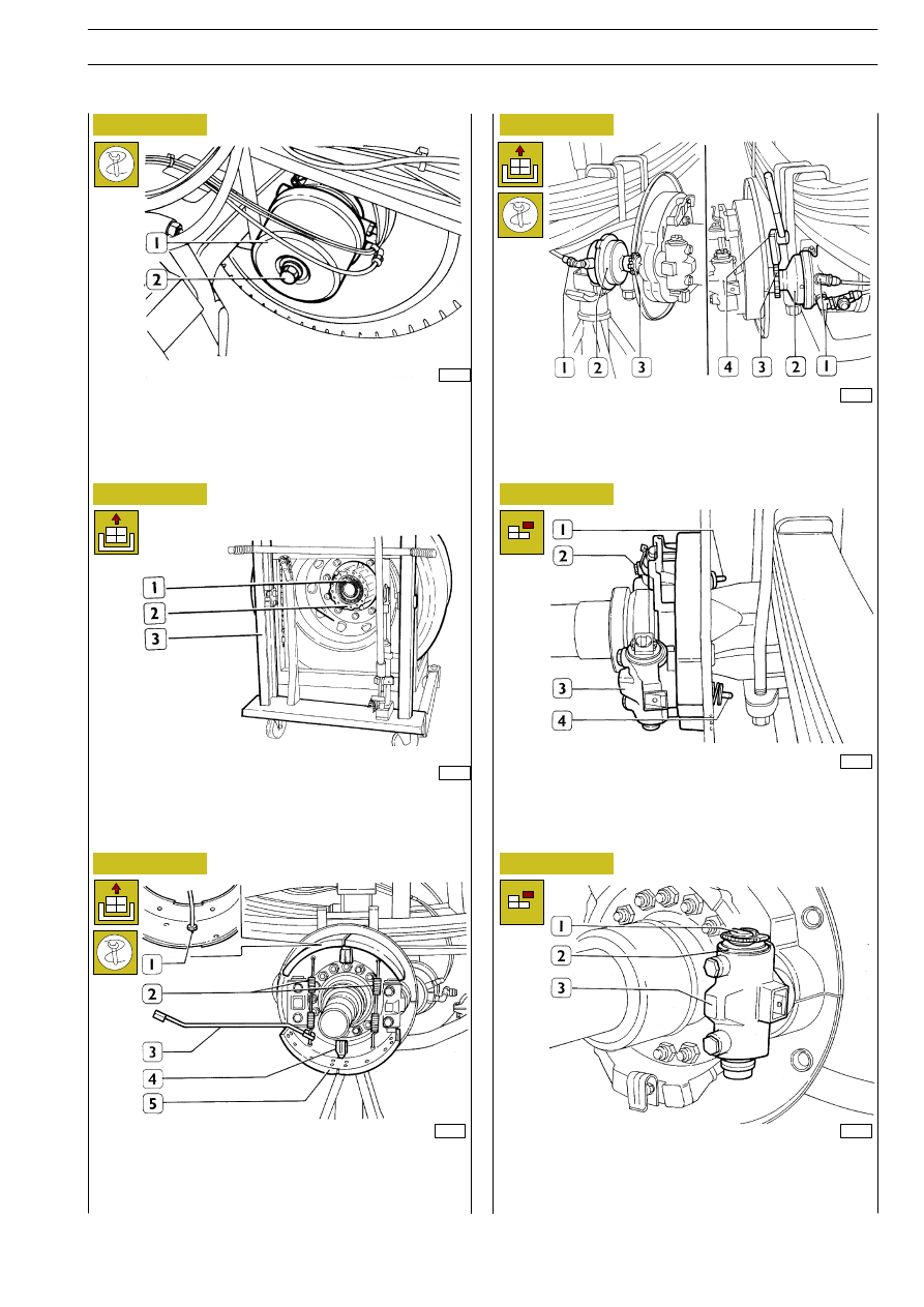
Before detaching the complete wheels, completely unscrew
manual unbraking screw (2) of combined cylinder (1).

38352

38704

38354

38355

Figure 150

Figure 151

Figure 152

Figure 153

Figure 154

Figure 155

With the help of tool 99372217 (3), detach jaws (4) checking
springs (2); detach jaws (4) from check brackets (5) after
having detached braking gaskets wear sensor (1).

Detach brake cylinders supply fittings (1). With wrench (4)
99356006 unlock ring nuts (3) and detach cylinders (2).

Withdraw control wedge units (1 and 4) from brake body (2
and 3).

With the help of a screwdriver, undrive metal ring (2) and
withdraw complete adjustment unit (1) from brake body (3).

36745

17243

By using hydraulic trolley 99321024 (3), detach wheel
completed with drum (2) and bearing (1).

E

URO

C

ARGO

T

ECTOR

12-26 t

PNEUMATIC SYSTEM - BRAKES

105

Base - February 2003

Unscrew guiding pin (2) from small piston (1) and extract the
piston from the brake body. With a screwdriver, undrive metal
ring (4).
Unscrew guiding pin (3) of thrust pin (5) and extract this latter
one from brake body.

38356

38357

38358

38359

38360

Figure 156

Figure 157

Figure 158

Figure 159

Figure 160

Withdraw sealing gaskets (2) from thrust pins (1).
Accurately clean all single parts composing the braking
assemblies.

Check the wear status of adjustment pins (2) and thrust pins
(1) sliding surfaces, further check chutes (3) surfaces on which
jaws opening control rollers operate.

Check guide pins (3) toothing wear status, integrity of related
compression springs (2) and copper washers (1).

Examine the wear status of drums and braking joints: if they
show scoring, braking surface damages, ovalities or eccentricity
greater than 0.25 mm, they must be turned.
If braking gaskets show a thickness that is lower than the
provided one, proceed with their replacement.
If the gasket braking surface shows traces of grease, it is
necessary to discover the reason for grease or oil seepage into
the braking unit, and then remove it.

Proceed with disassembling the wheel completed with hub,
and the whole braking unit on the opposite side, keeping the
component parts separated.

Check of component parts

Divide the automatic adjustment units.
Unscrew adjustment bushes (3) from adjustment pins (2), then
withdraw sealing gaskets (1).
Verify the external helical toothing wear status of adjustment
bushes, make sure of the regular sliding of bushes when
screwing them on related adjustment pints.

E

URO

C

ARGO

T

ECTOR

12-26 t

106

PNEUMATIC SYSTEM - BRAKES

Base - February 2003

Check wear status of seats on brake bodies (1); if they show
scorings or excessive wears, replace anomalous brake bodies.
Visually check ring (2) diameter, that is free from dents or
accidental abrasions; if necessary replace it following the
procedure described in the ”Rear axle” section.
Replace internal wheel hub gaskets.

38361

35713

Figure 161

Figure 162

Figure 163

Figure 164

Check that wedge units easily slid and parts do not show
abrasions.

!

In case of wear of parts composing wedge units, the
complete wedge unit must be replaced.

Insert on lathe 99301001 shaft (3) the drum (1) completed with
wheel centring it with suitable centring bushes.
Key-in on the shaft a series of spacers that remove axial
assembly clearance, screw the locking nut and apply the lathe
support.

17252

Measure drum diameter by using a sliding gauge without
angling the arms, measure the diameter in many points to
establish ovality and wear status.

17253

Carry out the turning operation by gradually operating till
imperfections on drum braking surface are removed.
Disassemble complete wheel from lathe, carry out an accurate
blowing operation on brake drum.

!

The maximum diameter increase allowed in drums is 4
mm. This limit must absolutely not be exceeded since
braking effect and drum resistance characteristics would
otherwise be impaired.

Couple adequate braking gaskets for every single
drum depending on the increase. Every vehicle axle
must be equipped with gaskets of the same type.

E

URO

C

ARGO

T

ECTOR

12-26 t

PNEUMATIC SYSTEM - BRAKES

107

Base - February 2003

DRUM TURNING

Carry out worn braking gaskets detachment from jaws by using
the compressed air press 99305087 (1).
Place complete jaws (4) on adjustable abutment plat (5).
With chisel (2) inserted in press (1) operating head, shear
rivets (3) heads.
Expel rivets from jaws.
Accurately clean the jaws by washing and blowing them.

Apply on mobile press support (4) the abutment pin (5).
Proceed with nailing braking gaskets (3) on jaws (2) by using
beater (1) inserted in press operating head.

38362

38363

17255

35713

Figure 165

Figure 166

Figure 167

Assemble jaws (1) on table (3) of lathe 99301006, and lock
them with handles (2).

Reset tool (1) operating on handwheel (2) and proceed with
turning.

!

Brake jaws turning can also be carried out by using
tool 99372228 on lathe 99301001.

!

The correct execution of braking gaskets nailing is
carried out starting from the center, and gradually
extending it outside of braking sectors.

!

Visually check that jaws do not show cracks; if they are
detected, replace anomalous jaws.

Figure 168

E

URO

C

ARGO

T

ECTOR

12-26 t

108

PNEUMATIC SYSTEM - BRAKES

Base - February 2003

BRAKING GASKETS REPLACEMENT

527233

BRAKING GASKETS TURNING


Content   ..  188  189  190  191   ..