Iveco EuroCargo (12 to 26 t). Manual - part 129
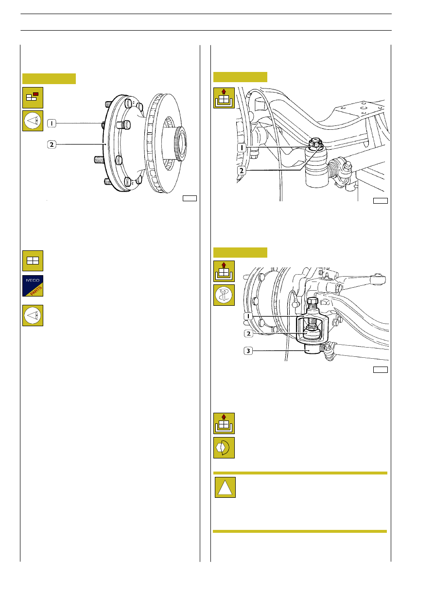
Figure 36
Figure 37
Use general tools to pull out stud bolts (1) from the brake
disc (2).
Check that the head supporting plane of the stud bolts is not
burred.
33004
Use extractor (1) 99347068 to unlock the steering head (3)
from the lever (2). Repeat the same operations on the oppo-
site side, release the nuts completely and remove the cross tie
rod.
33006
!
Figure 38
Straighten and take off the split pin (1).
Unlock the nut (2) and release it partially in order to prevent
the tie rod from falling when it is removed.
33005
520635
CROSS TIE ROD REMOVAL AND
REFITTING
520625
REPLACEMENT OF STUD BOLTS
FOR WHEEL CLAMPING
Check that the nut grooves match with the cross
holes on the conical pins. If it is not possible to intro-
duce the split pins, gradually raise the nut tightening
torque until the split pins are completely put in place
(angle lower than 60
°).
Place the stud bolts accurately and put on their
head a load not higher than:
- 2300 kg for axle 5842/5
- 2500 kg for axle 5851/5
Once the operation is completed, check that there
is no clearance between the disc plan and the area
below the stud bolt head. Check also that the ort-
hogonality error is not higher than 0.3 mm.
To reattach reverse the detachment operation or-
der.
Clamp the conical pin castellated lock nuts with the
requested torque.
E
URO
C
ARGO
T
ECTOR
12-26 t
60
FRONT AXLES 5842/5 - 5851/5
Base - February 2003