Iveco EuroCargo (12 to 26 t). Manual - part 28
70499
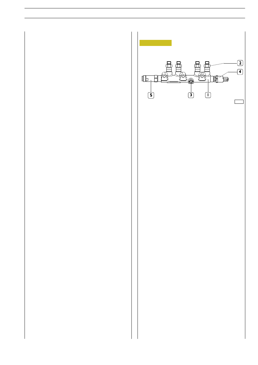
Figure 215
Operation
The cylinder is filled through the cap intake valve only if the
supply pressure is suitable to open the delivery valves set on
the pumping elements (about 2 bars).
The amount of fuel supplying the high-pressure pump is
metered by the pressure regulator, placed on the
low-pressure system; the pressure regulator is controlled by
the EDC7 control unit through a PWM signal.
When fuel is sent to a pumping element, the related piston
is moving downwards (suction stroke). When the piston
stroke is reversed, the intake valve closes and the remaining
fuel in the pumping element chamber, not being able to come
out, is compressed above the supply pressure value existing
in the rail.
The thereby-generated pressure makes the exhaust valve
open and the compressed fuel reaches the high-pressure
circuit.
The pumping element compresses the fuel till the top dead
center (delivery stroke) is reached. Afterwards, the pressure
decreases till the exhaust valve is closed.
The pumping element piston goes back towards the bottom
dead center and the remaining fuel is decompressed.
When the pumping element chamber pressure becomes less
than the supply pressure, the intake valve is again opened and
the cycle is repeated.
The delivery valves must always be free in their movements,
free from impurities and oxidation.
The rail delivery pressure is modulated between 250 and
1350 bars by the electronic control unit, through the
pressure regulator solenoid valve.
The pump is lubricated and cooled by the fuel.
The radialjet pump disconnection — reconnection time on
the engine is highly reduced in comparison with traditional
injection pumps, because it does not require setting.
If the pipe between fuel filter and high-pressure pump is to
be removed-refitted, be sure that hands and components are
absolutely clean.
1. Rail. — 2. Flow limiters. — 3. Fuel inlet from high-pressure
pump. — 4. Pressure sensor. — 5. Overpressure valve.
The rail volume is of reduced sizes to allow a quick
pressurisation at startup, at idle and in case of high flow-rates.
It anyway has enough volume as to minimise use of plenum
chambers caused by injectors openings and closings and by
the high-pressure pump operation. This function is further
enabled by a calibrated hole being set downstream of the
high-pressure pump.
A fuel pressure sensor (4) is screwed to the rail. The signal
sent by this sensor to the electronic control unit is a
feed-back information, depending on which the rail pressure
value is checked and, if necessary, corrected.
RAIL
E
URO
C
ARGO
T
ECTOR
12-26 t
ENGINE F4 AE 0481
109
Base - February 2003