Iveco EuroCargo (12 to 26 t). Manual - part 25
62873
70490
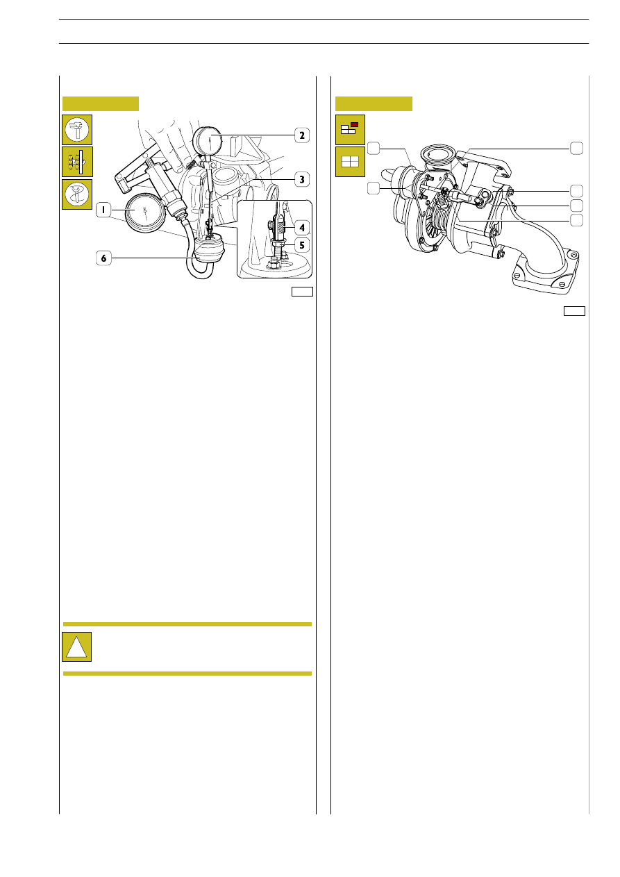
Figure 199
Figure 200
Cover the air, exhaust gas and lubrication oil inlets and
outlets.
Carry
out
an
accurate
external
cleaning
of
the
turbosupercharger, using the anticorrosive and antioxidant
solution and perform the check on the actuator (6).
Clamp the turbosupercharger in a vice.
Disconnect the pipe of the actuator (6) and apply to the
actuator union, the pipe of pump 99367121 (1).
Apply the magnetic-base dial gauge (2) on the exhaust gas
inlet flange in the turbine.
Position the tracer point of the gauge (2) on the tie rod (3)
end and set to zero the gauge (2).
Through the pump (1) let in compressed air, in the actuator
(6), at the prescribed pressure and make sure that such value
is kept constant for the whole check time, otherwise replace
the actuator (6).
In the above-mentioned conditions, the tie rod must have
carried out the prescribe stroke.
Check and adjustment
If a different value is found, loosen the nut (5) and operate
properly the knurled ring nut (4).
Remove the elastic clip (4) and withdraw the tie rod (3) from
the lever (5).
Remove the nuts (2) and remove the actuator (1) from the
supporting bracket. Fit the new actuator following the re-
moval operations in reverse order and fitting a new clip (4),
tighten the nuts (2) to 5.6 — 6.8 Nm torque.
Check and adjust the actuator (1), if required, as described
in the relevant chapter.
Then, paint the nut (6) with safety paint.
Before refitting the turbosupercharger on engine, fill the
central body with engine oil.
Actuator replacement
!
During the operation, beat slightly the actuator (6)
in order to eliminate possible sticking of the actuator
internal spring.
1
2
3
4
5
6
E
URO
C
ARGO
T
ECTOR
12-26 t
ENGINE F4 AE 0481
93
Base - February 2003
TURBOSUPERCHARGER ACTUATOR