Iveco Stralis AT/AD. Manual - part 261


  Index      Iveco     Iveco Stralis AT/AD - service repair manual 2003 year


Search            


Content   ..  259  260  261  262   ..


Iveco Stralis AT/AD. Manual - part 261


Press (

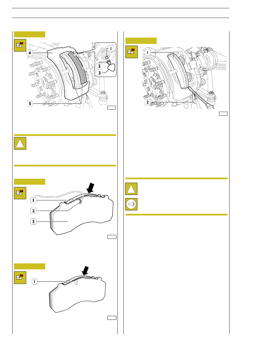
→) on the spring (1) and remove it. Remove the wear

sensors (2) from the brake linings (3).

78623

Figure 89

For vehicles without EBS

49160

For vehicles with EBS

60862

Press (

→) on the spring (1) and remove it. If necessary, replace

it with a new one.

For all vehicles

49161

!

Visually check the conditions of the dust caps, if
deformed or broken it is necessary to replace them.
This requires removing the brake calliper, so it is
recommended to remove the brake calliper body
together with the bearing plate for a thorough
overhaul.

Check that the calliper slides freely on its guides.
If you find any trouble on a single brake calliper it is wise to
overhaul both brake callipers completely.
Remove the dirt from the brake calliper with a wire brush,
without damaging the dust caps.
Clean the sliding surfaces of the brake linings.
Check the conditions of the brake disc and make sure it is not
corroded, scored or grooved. Light surface cracks are
acceptable, but it is necessary to grind the brake disc as
described under the relevant section heading. On the
contrary, if it is worn, replace the brake disc.
If one needs to be replaced, it is recommended to replace
both brake discs.
Check the state of the springs and wear sensors, replace them
if necessary.

Figure 90

Figure 91

Figure 92

Remove dirt and rust from around the edge of the brake disc
with a scraper or an old screwdriver (2) resting on the calliper
body, turning the disc (1).
Finish the job with abrasive cloth. Remove the remains with
the aid of an aspirator, or rags and a brush.
Do not use petrol or other petroleum products that could
cause trouble for the brakes.
Use only methylated spirit or isopropyl alcohol.
Carefully clean the surfaces of the braking area of the brake
disc.

Remove the plug (3). Turn the adjustment device (1)
operating on the adapter counterclockwise with a wrench, to
insert the pistons within the caliper body and extract brake
linings (4), suitably moving the caliper body (3).

!

Never operate directly on the registration pinion (1)
without having first of all fitted the adapter (2). If the
cutting torque of the adapter is exceeded, this will
break.
Test with a new adapter. If this also breaks, the caliper
must be replaced because it is damaged.

S

TRALIS

AT/AD

102

AIR SYSTEM - BRAKES

Base - January 2003

For vehicles without EBS

49162

Figure 93

Insert the wear sensor (2) into its seat on the brake lining (3).
Mount the spring (1) in the opposite sequence to that for
disassembly.

For vehicles with EBS

60863

Figure 94

Mount the spring (1) in the opposite sequence to that for
disassembly.

For all vehicles

49163

Figure 95

Insert the new linings in the brake calliper (1) and check they
slide freely in their seats.

!

If you find it necessary to replace the pair of brake
linings, always replace them with a full set for each
axle.

78624

Figure 96

For vehicles without EBS

49158

Figure 97

Make the electrical connection (1) and secure it to the calliper
body.
Mount the plate (4), pin (3) and split pin (2).

Using the wrench (1), act on the adaptator retriever pin to get
a play not lower than 0.7 mm between brake lining and brake
disk, which can be measured using the thickness gauge (2).
Replace the cover (4) and lubricate it with white grease
RENOLIT HLT2.

!

Make sure that the outer protecting plug and the seal
ring are correctly fitted, in order to prevent water
leaks inside the play automatic retriever.

AIR SYSTEM - BRAKES

103

S

TRALIS

AT/AD

For vehicles with EBS

60860

Figure 98

Mount the plate (3), pin (2) and split pin (1).

For vehicles without EBS

49165

Figure 99

Mount the wear sensor cable retaining plate (1).
Using the hydraulic trolley 99321024, fit on the wheels. Lower
the vehicle. Lock the nuts fixing the wheels to the required
torque.
Fit the safety cap onto the wheel hubs.
Proceed as described on the opposite side.
After repairing the vehicle brakes, press the brake pedal
repeatedly, while the vehicle is moving, in both directions, in
order to wear in the brake linings.

527413

Removing and refitting brake callipers
Removal

For vehicles without EBS

49166

Figure 100

To remove the brake linings, keep to the above description in
the paragraph for replacing brake linings. Remove the clamps
(2). Disconnect the diaphragm cylinder supply pipe (1).
Unscrew the nuts (4) and remove the diaphragm cylinder (3).

For vehicles with EBS

60866

Figure 101

To remove the brake linings, keep to the above description in
the paragraph for replacing brake linings. Remove the clamps
(2). Disconnect the diaphragm cylinder supply pipe (1).
Unscrew the nuts (4) and remove the diaphragm cylinder (3).
Disconnect the electrical connection (5) of the calliper body.

!

Nuts (4) are to be discarded.

!

Nuts (4) are to be discarded.

S

TRALIS

AT/AD

104

AIR SYSTEM - BRAKES

Base - January 2003

For all vehicles

49167

Figure 102

Remove the screws (3) and disconnect the brake calliper (1)
together with the bearing plate (2).

77206

Figure 103

Rotate wheel hub in order to take screw plug (1) downwards;
unscrew the plug and drain oil into a suitable tank.

Refitting

For refitting, carry out the steps described for
removal in reverse order, keeping to the required
tightening torques.

520620

Removing and refitting wheel hubs

Removal

36407

Figure 104

Block rotation of the wheel hub appropriately and, using the
wrench 99354207 (1), unscrew the oil cover (2).
Drain off all the oil.

36408

Figure 105

Undo the safety screw (3). With the wrench 99388001,
unscrew the adjustment ring nut (2), remove the washer (4),
outer bearing (1) and remove the brake disc together with the
wheel hub, spacer and internal bearing.

38596

Figure 106

Visually check the diameter of the gasket ring (1) has no
accidental dents or scratches.
Replace the internal gaskets of the wheel hubs and, if
necessary, the ring (1), keeping to the description given in the
”Front axle” section.
Using the adjustment ring nut, check that the thread (2) has
no stiffness. If it has, use appropriate means to get rid of the
stiffness.
Remove

the opposite

brake assembly,

keeping the

components separate.

!

Be very careful in removing and carrying the calliper
(1) as it is heavy and floating on the support plate (2).
Keep the caliper only on the outer side. Never put
your fingers between the caliper (9) and the
supporting plate.

AIR SYSTEM - BRAKES

105

S

TRALIS

AT/AD


Content   ..  259  260  261  262   ..