Iveco Stralis AT/AD. Manual - part 256
Since the vehicle system is type approved to European code standards, it is vital to periodically check its efficiency and that of
the relevant components with the device 99305117.
These checks should be carried out with the vehicle stationary, using the compressed air of the tanks filled by the compressor,
with the engine started.
!
Always lock the vehicle before doing any work. Periodically check the pressure gauges, comparing them with a sample
pressure gauge.
(continued)
S
TRALIS
AT/AD
82
AIR SYSTEM - BRAKES
Base - January 2003
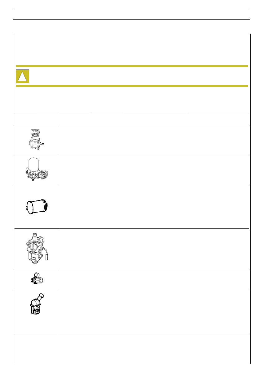
DEVICE
DESCRIPTION
TASK
Compressor
Check the tightness of fittings and compressor fixing; make sure the
cooling fins are not dirty.
A.P.U.
(Air Processing Unit)
Using a bleed valve or loosening a screw plug (with integrated bleed
hole), check whether the air drier works properly. In this case, the
air needs to come out of the tank without there being any trace of
condensation water.
Air tanks for:
- Front axle
- Rear axle
- Parking + trailer
- Services
- For regeneration
Check the seal and corrosion protection.
Drain the condensate off from the tanks via the drain valve.
Duplex control valve
Check that the pedal gasket is not worn, that the brake control
linkage is properly tightened and lubricated, not out of shape. Check
that the lever housings are neither worn nor oxidized.
Pneumatic pressure
test points
Check the safety caps are on
Parking brake control valve
Apply the parking brake control valve till it trips; the pressure gauge on
the test point has to show pressure discharge down to 0 bar in 1 sec.
Parking brake control valve
(with check position)
At the same time, at the automatic coupling pipe, the pressure gauge
has to show a pressure of 7.5 bars.